 Vespa Primavera 50 - Service manual > Automatic transmission
Transmission cover
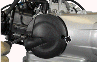
- Remove the air duct.
- Remove the plastic cover that has the vehicle logo on it.
- Insert the specific tools, rotate the engine until the driven pulley stops and remove the nut, recovering the washer.
Specific tooling
020937Y Driven pulley lock
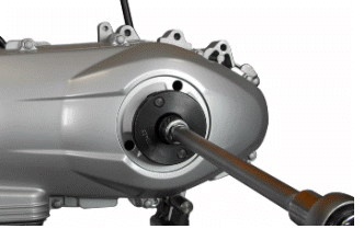
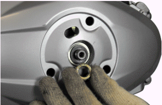
- Unscrew the ten screws fixing the engine and remove the transmission cover.
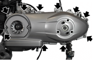
Air duct
- Remove the plastic cover.
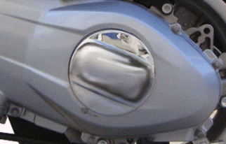
- Unscrew the two screws indicated and remove the duct.
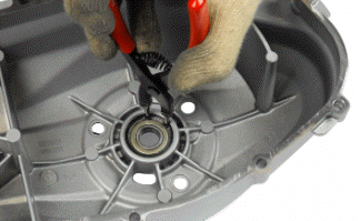
Removing the driven pulley shaft bearing
- Remove the Seeger ring.
CAUTION
PLACE THE COVER ON A SURFACE, REMOVING OR EXCLUDING THE ALIGNMENT DOWELS.
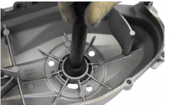
- Support the transmission cover adequately.
- Using appropriate tools, remove the bearing.
Specific tooling
020376Y Adapter handle
020357Y 32 x 35 mm adaptor
020412Y 15 mm guide
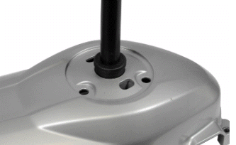
Refitting the driven pulley shaft bearing
- Use the heat gun to heat the inner part of the lid.
- Using the equipment plant a new bearing, apply grease on the adapter and guide in order to maintain the position of the bearing during operation on the vertical axis.
Specific tooling
020151Y Air heater
020376Y Adapter handle
020358Y 37 x 40 mm adaptor
020412Y 15 mm guide
- Insert the Seeger ring.
- Insert the alignment dowels if removed during disassembly.
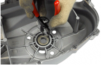
Removing the driven pulley
- Undo the clutch fixing screw, recovering the lining.
- Remove the clutch drum.
- Remove the driven pulley.
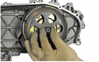
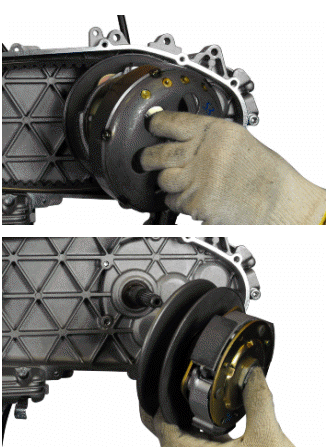
Inspecting the clutch drum
- Make sure that the clutch bell is not worn or damaged.
- Measure the clutch bell inside diameter.
Characteristic
Clutch bell max. value
Max. value: Ø 134.5 mm
clutch housing standard value
Standard value: Ø 134 to 134.2 mm
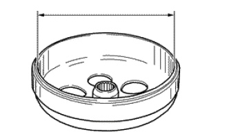
Checking the bell working surface eccentricity
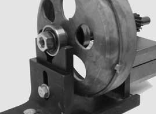
- Fit the bell on a driven pulley shaft with 2 bearings (inside diameter: 15 and 17 mm).
- Lock with the original spacer and nut.
- Place the bell/shaft assembly on the support to check the crankshaft alignment.
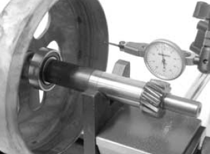
- Using a dial gauge and the magnetic base, measure the bell eccentricity.
- Repeat the measurement at 3 positions (Central, internal, external).
- In case of faults, replace the bell.
Specific tooling
020074Y Support base for checking crankshaft alignment
020335Y Dial gauge magnetic support
Characteristic
clutch bell check: Limit eccentricity.
Admissible limit eccentricity: 0.15 mm
Removing the clutch
- Prepare the locking tool for the driven pulley with the pins half-screwed in the tool set to "C".
- Introduce the adapter ring 11 with the chamfering facing the inside of the tool.
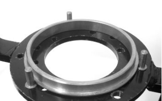
- Fit the driven pulley unit in the tool so as the bolt get into the masses clutch support holes. Afterwards make the support screw make contact with a minimum force.
- Using the specific wrench, inserted 46 mm from the side, remove the clutch central locking nut.
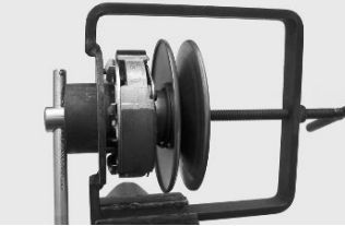
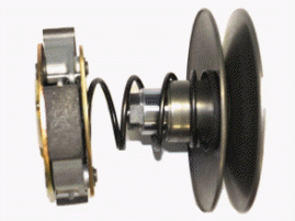
- Separate the components of the driven pulley.
CAUTION
THE TOOL MUST BE FIRMLY FIXED IN THE VICE AND THE CENTRAL SCREW MUST NOT BE TIGHTENED WITH EXCESSIVE TORQUE AS THIS MAY DAMAGE THE PULLEY OR DEFORM THE SPECIFIC TOOL.
Specific tooling
020444Y Tool for fitting/removing the clutch on the driven pulley
020444Y011 adapter ring
020444Y009 wrench 46 x 55
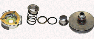
Inspecting the clutch
- Check the thickness of the clutch mass friction material.
- The masses must exhibit no traces of lubricants; in that case, check the driven pulley unit seals.
N.B.
UPON RUNNING-IN, THE MASSES MUST EXHIBIT A CENTRAL FAYING SURFACE AND MUST NOT BE DIFFERENT FROM ONE ANOTHER.
DIFFERENT CONDITIONS MAY CAUSE CLUTCH TEARING.
CAUTION
DO NOT USE TOOLS TO OPEN THE MASSES TO AVOID VARIATION IN THE RETURN SPRING LOAD.
Characteristic
Check minimum thickness
1 mm
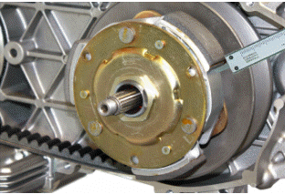
Pin retaining collar
- Simultaneously turn and pull the collar manually to remove it.
N.B.
USE TWO SCREWDRIVERS IF YOU HAVE ANY DIFFICULTY.
N.B.
BE CAREFUL NOT TO PUSH THE SCREWDRIVERS IN TOO FAR TO AVOID DAMAGE THAT COULD COMPROMISE THE O-RING SEAL.
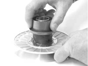
Removing the driven half-pulley bearing
- Remove the retainer ring using two flat blade screwdrivers.
- Using a hammer and pin, knock the ball bearing out as shown in the figure.
- Remove the bearing and the rollers with the specific extractor.
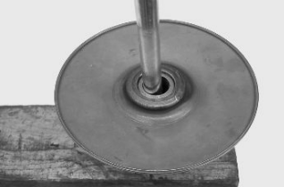
N.B.
REST THE HALF-PULLEY ON A WOODEN SURFACE TO AVOID DAMAGING ITS THREADED BUSHING. ALSO DO THIS UPON REMOVAL.
Specific tooling
001467Y008 Calliper to extract 17-mm diameter bearings
001467Y009 Bell for OD 42-mm bearings
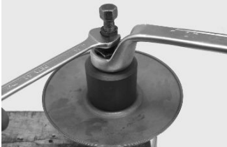
Inspecting the driven fixed half-pulley
- Measure the outside diameter of the pulley bushing.
Characteristic
Standard diameter:
Ø 40.1 +- 0.05 mm
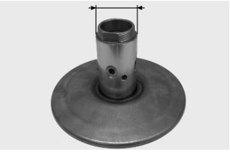
Refitting the driven half-pulley bearing
- Fit the new roller bearing using the specific punch, fit the bearing with the label facing outward and insert it completely up to the punch stop on the half-pulley.
N.B.
REST THE HALF-PULLEY ON A WOODEN SURFACE TO AVOID DAMAGING ITS THREADED BUSHING. ALSO DO THIS UPON REMOVAL.
Specific tooling
020424Y Punch for fitting driven pulley roller casing
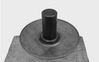
- To assemble the new ball bearing, insert it fully down in its seat with the specific punch and finally fit the seeger ring.
Specific tooling
020375Y 28 x 30 mm adaptor
020376Y Adapter handle
020439Y 17 mm guide
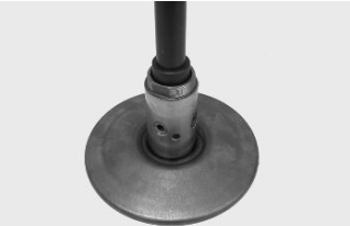
Refitting the driven pulley
- Check that the faying surfaces of the 2 half-pulleys and the belt do not show any signs of wear, scoring or grease.
- Insert the new oil seals and O-rings on the movable half-pulley.
- Fit the half-pulley on the bushing with the appropriate protection sheath.
- Make sure the pins and collar are not worn, refit the pins and the collar.
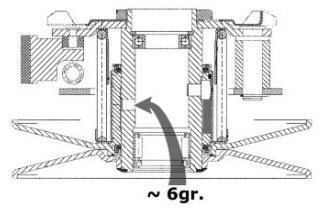
- Using a curved-spout grease gun, lubricate the driven pulley unit with
approximately 6 g of grease.
Apply the grease through one of the holes in the bushing until grease comes out through the hole on the opposite side. This procedure is necessary to prevent the presence of grease beyond the O-rings.
Specific tooling
020263Y Sheath for fitting the driven pulley
Recommended products
AGIP GREASE SM 2 Gray black smooth-textured lithium grease, containing
molybdenum disulphide.
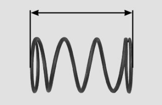
Inspecting the clutch spring
Measure the length of the movable driven half-pulley spring, when unloaded.
Characteristic
Standard length:
106 mm
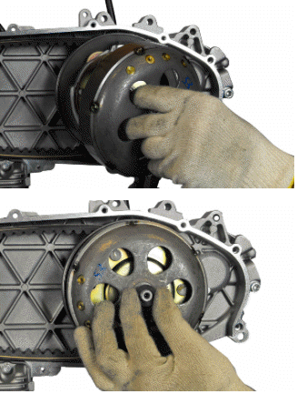
Refitting the driven pulley
- Reassemble the clutch housing and spacer.
See also:
 Vespa Primavera 50 - Service manual > Engine
N.B. THE UNITS OF MEASUREMENT CONTAINED IN THIS CHAPTER ARE EXPRESSED IN TERMS OF THE DECIMAL METRIC SYSTEM. TO REFER TO THE UNIT OF MEASUREMENT EXPRESSED IN TERMS OF THE ANGLO-SAXON SYSTEM, SEE THE "CHARACTERISTICS" CHAPTER.
 Vespa Primavera 50 - Service manual > Drive-belt
Make sure the drive belt is not damaged and does not show signs of abnormal wear. Replace according to the scheduled maintenance table. Removing the driving pulley Using specific tools, lock the driving pulley and loosen the nut.
 BMW R 1250 RT
 Kymco Agility 50
 Piaggio Liberty 50
 Yamaha aerox NS50
 Aprilia SR50R
 Kymco Agility 50
 Vespa Primavera 50
 Peugeot Speedfight