 Aprilia SR50R - Service manual > Engine C 364
REMOVING THE ENGINE C 364
- Remove the air box hose.
- Remove the brake caliper, see (REMOVING THE BRAKE CALIPER).
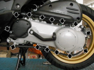
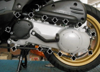
- Loosen and remove the fifteen screws and remove the converter cover.
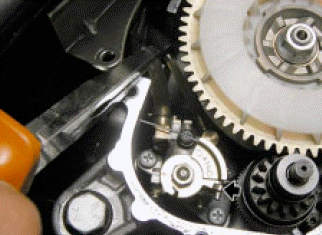
- Release the mixer oil pump drive cable.
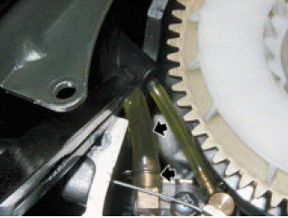
- Pinch the oil hose delivery.
- Remove the tie and the hose.
- Remove the carburetor, see (REMOVING THE CARBURETOR).
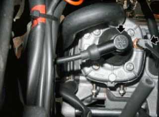
- Remove the spark plug cap.
- Disconnect the temperature sensor connector.
- Remove the two rear side panels, see (REMOVING THE REAR SIDE PANELS).
- Remove the exhaust, see (REMOVING THE EXHAUST).
- Disconnect the alternator connector.
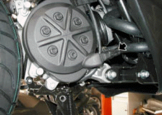
- Loosen and remove the four screws.
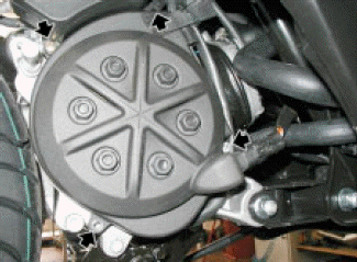
- Remove the tie and the cover.
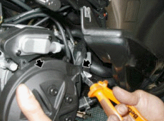
- Loosen and remove the two upper screws securing the lower cover.
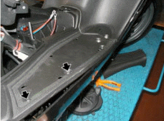
- Loosen and remove the lower screw of the lower cover.
- Slide down the lower protection.
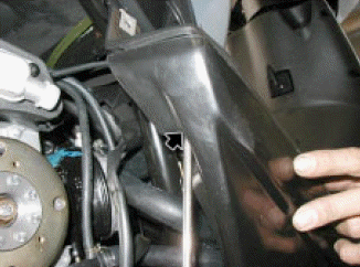
- Loosen and remove the screw and remove the starter motor ground cables
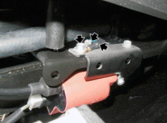
- Remove the clamp.
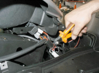
- Disconnect the connector.
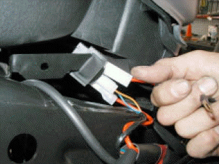
- Loosen and remove the drain screw of the cooling system and drain it.
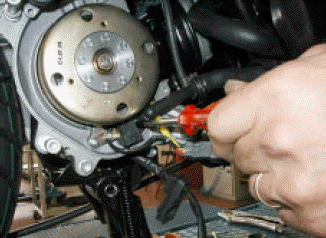
- Loosen the clamp and remove the hose on the thermostatic valve end.
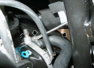
- Using a belt and a suitable tool, lift the vehicle rear end.
- Remove the rear shock absorber lower screw, see (REMOVING THE REAR SHOCK ABSORBER).
- Working on the right side, loosen and remove the nut.
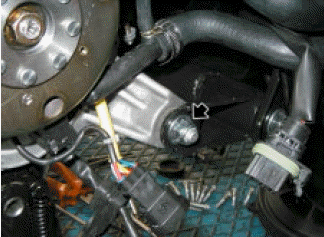
- Working on the opposite side, remove the pin.
- Remove the engine.
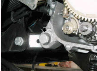
INSTALLING THE ENGINE C 364
- Move the frame in small motions until the holes match perfectly.
- Insert the pin.
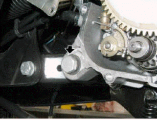
- Working on the right side, fit and tighten the nut.
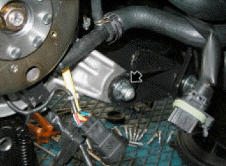
- Fit the hose in the thermostatic valve.
- Fit a new clamp and tighten.
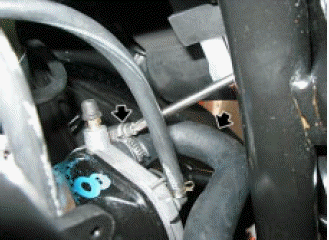
- Fit and tighten the drain screw.
- Fill the cooling system.
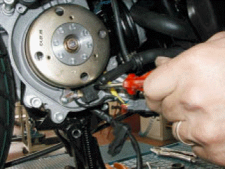
- Connect the connector.
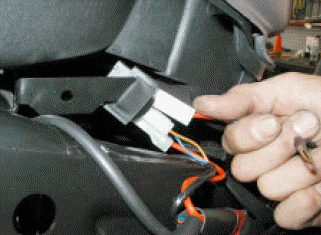
- Fit a new clamp to the wiring.
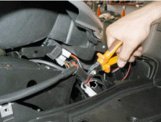
- Position the starter motor ground cables.
- Fit and tighten the screw.
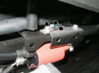
- Fit the lower protection.
- Fit and tighten the lower screw of the lower cover.
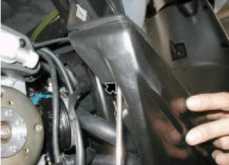
- Fit and tighten the two upper screws securing the lower cover.
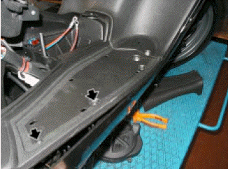
- Fit cover.
- Fit and tighten a new clamp.
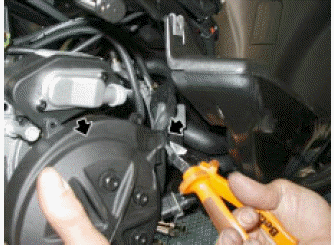
- Fit and tighten the four screws.
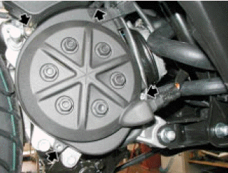
- Connect the alternator connector.
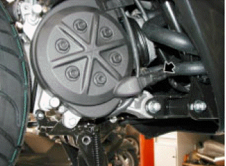
- Connect the temperature sensor.
- Fit the spark plug cap.
- Install the exhaust.
- Install the two rear side panels.
- Install the carburetor.
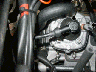
- Fit the hose to the mixer oil pump.
- Fit the clamp.
- Pinch the oil hose delivery.
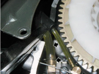
- Fit the mixer oil pump drive cable.
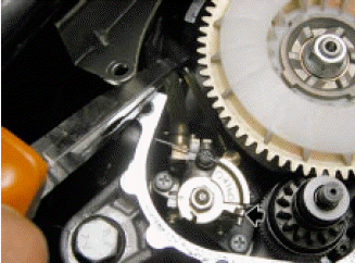
- Fit the converter cover.
- Fit and tighten the fifteen screws.
- Fit the rear brake caliper.
- Fit the air box hose.
SECONDARY AIR SYSTEM
SYSTEM DIAGRAM
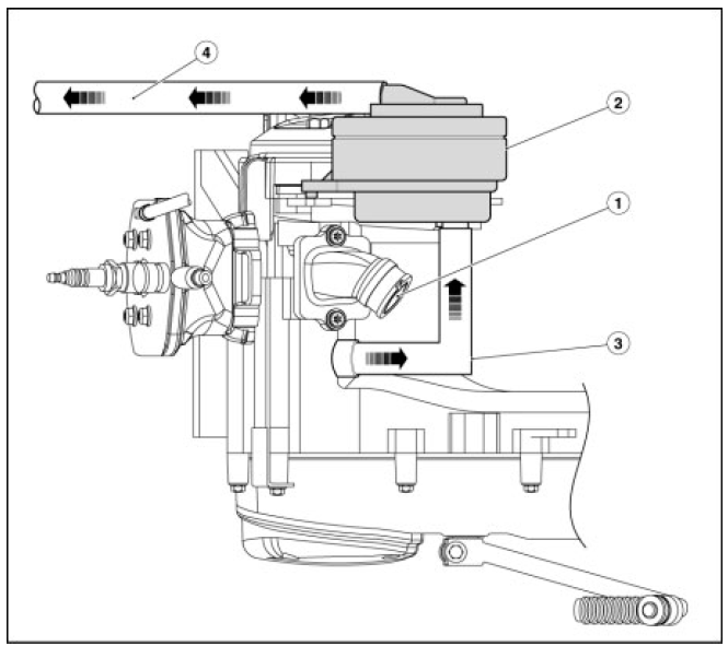
Key:
- Intake manifold;
- Secondary air valve;
- From the engine;
- Exhaust.
SAS
The Secondary Air System (SAS) has been developed to reduce carbon oxide and unburnt hydrocarbon emissions in vehicles that are not equipped with a lambda sensor. Natural air (which is rich in oxygen) is channelled into the exhaust stream to trigger a post-combustion process that raises the temperature of the exhaust gasses for a quick light-off of the catalyst. The secondary air system is especially useful when the engine is idling and during warm-up, since the catalyst alone is not capable of triggering post-combustion under these operating conditions.
DESCRIPTION OF THE SYSTEM
The secondary air system operates on pressure fluctuation in the exhaust system. During depression stages, the exhaust takes in oxygen-rich air from the secondary air system so unburnt gasses in the exhaust stream can complete the combustion. During overpressure stages, the secondary air reed valve cuts air supply to prevent backflow. On 4-stroke engines, the reed valve is equipped with a cut- off device that shuts down additional air during cut-off stages, as exceedingly lean exhaust gasses would lead to exhaust blowing, resulting in exhaust valve and catalytic converter damage.
DETAILS OF SAS
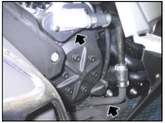
- The system consists of a rubber hose that takes filtered air in through a scoop on the casing.
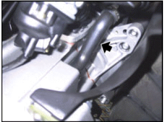
- Secondary air flow is controlled by a reed check valve, on the vehicle right-hand side, on the flywheel cover.
- The secondary air tube is connected to a flanged metal fitting attached directly to the head exhaust duct.
REMOVING AND CLEANING THE AIR FILTER
- Loosen the two screws and remove the aluminum cover of the system.
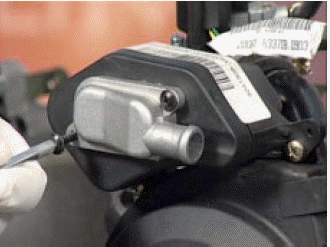
- Remove the plastic cover and the filter.
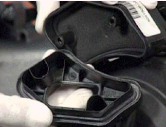
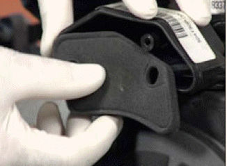
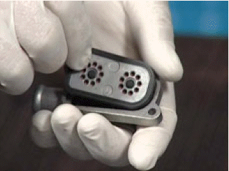
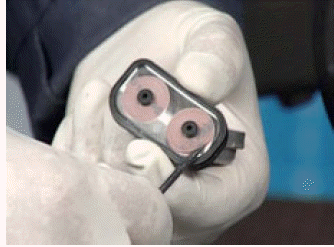
- Remove the single-acting valve housing, check the valve condition and refit them in their housings.
- Wash and blow the filter with compressed air.
See also:
 Aprilia SR50R - Service manual > Engine IE 50
REMOVING THE ENGINE IE 50 To remove the crankcase, first remove the lower shield, the battery, the fuel tank, the throttle body, keep it connected to the throttle cable and drain the cooling system. Using a belt and an A-frame, lift the vehicle rear end. Loosen and remove the shock absorber upper screw. Loosen and remove the two cable guide screws. Loosen and remove the two screws. Slide out the rear brake caliper, keep it connected to the fluid line. Slide the two intake hoses out of the ties on the frame.
 BMW R 1250 RT
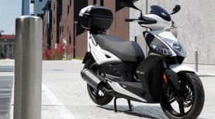 Kymco Agility 50
 Piaggio Liberty 50
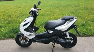 Yamaha aerox NS50
 Aprilia SR50R
 Kymco Agility 50
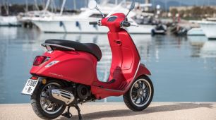 Vespa Primavera 50
 Peugeot Speedfight