 Vespa Primavera 50 - Service manual > Handlebar
Removal
Remove the handlebar cover before carrying out this operation,.
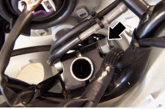
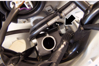
- After removing the transmissions and disconnecting the electrical terminals, remove the terminal fixing the handlebar to the steering.
- Check all components and replace faulty parts.
N.B.
IF THE HANDLEBAR IS BEING REMOVED TO REMOVE THE STEERING, TILT THE HANDLEBAR FORWARD TO AVOIDING DAMAGING THE TRANSMISSIONS.
WARNING
DO NOT LEAVE THE REMOVED INSTRUMENT DANGLING OR UPSIDE DOWN AS THIS COULD DAMAGE IT IRREPARABLY.
FAILURE TO OBSERVE THIS INSTRUCTION CAUSES THE LOSS OF CALIBRATION OF THE INSTRUMENT PANEL WHICH, ALTHOUGH OPERATIONAL, INDICATES INCORRECT VALUES.
Refitting
Carry out the removal operations but in the reverse order, observing the prescribed tightening torque.
Locking torques (N*m)
Handlebar lock nut 45 - 50
Steering column
Removal
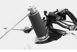
After removing the upper seat, lean the vehicle on one side and extract the steering tube completely from the fork.
Specific tooling
020055Y Wrench for steering tube ring nut
Overhaul
Servicing the front suspension-steering assembly, described below, deals mainly with replacing parts (pin- NADELLA roller bushings - sealing rings unit and dust gaiter) which connect the steering tube to the front wheel holder swinging hub.
N.B.
BEFORE PROCEEDING WITH THE DESCRIBED SERVICE, CHECK THAT THE STEERING TUBE AND THE WHEEL HOLDER HUB ARE IN EXCELLENT CONDITIONS: ONLY THEN IS THE SERVICE JUSTIFIABLE.
MOREOVER, REMEMBER THE STEERING TUBE SHOULD BE REPLACED WITH A NEW ONE WHEN DEFORMED.
a = Ø 12 Punch
b = Sharp-edged end
Use a suitable punch with the dimensions indicated on the figure; hit with a mallet until the wedging washer is crushed and then extract it with the help of a pointed end.
Repeat the operation for the second washer using the punch on the side opposite to the one shown in the figure.
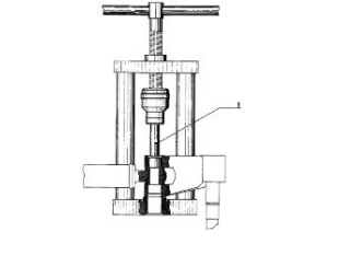
Use the tool fitted with part 1 as shown in the figure and move the tool handgrip until the pin and the NADELLA are simultaneously ejected in the direction opposite the tool thrusting force.
After removing the pin and the first NADELLA, the swinging hub gets detached from the steering tube.
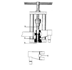
To remove the second NADELLA, use the tool fitted with part 2 instead of part 1, on the side opposite the one shown in the figure.
N.B.
DURING THE REMOVAL OPERATIONS DESCRIBED ABOVE, THE ROLLER BUSHINGS ARE DESTROYED WHEN THE EXTRACTOR IS USED. UPON REFITTING, IT IS THEREFORE NECESSARY TO USE NEW BUSHINGS AS WELL AS A NEW PIN, NEW SEALING RINGS AND DUST GAITER.
Specific tooling
020021Y Front suspension service tool
Connect the swinging hub to the steering tube with the guiding pin.
- Use the tool fitted with part 3 on the stem and part 4.
Lubricate the pin with recommended grease and insert it temporarily on the swinging hub, move the tool handgrip until part 3 is fully inserted on the steering tube.
After fitting the pin, insert the two spacers, slightly hitting them with the mallet.
N.B.
BEFORE PROCEEDING WITH THE DESCRIBED FITTING, PLACE THE TWO DUST GAITER RINGS ON THE SWINGING HUB AS SHOWN IN THE FIGURE.
Specific tooling
020021Y Front suspension service tool
Recommended products
AGIP GREASE SM 2 Gray black smooth-textured lithium grease, containing
molybdenum disulphide.
- Insert the sealing ring on the pin and the roller bushing with its wedging washer at the same time.
- Remove the tool and the part 5 (guide), which has been partially ejected during the previous pin fitting phase, and leave part 4 always fitted.
- Replace part 3 with part 16 (on the stem).
- By moving the tool handgrip, push the wedging washer - roller bushing - seal ring unit, placing part 16 until it stops on the swinging hub.
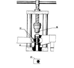
- Repeat the above operation using the tool with part 16 and part 22, instead of part 4, always fitted to the stem, on the side opposite that indicated in the figure to fit the second wedging washer - roller bushing - sealing ring unit.
WARNING
BEFORE PROCEEDING WITH THE DESCRIBED PRE-FITTING, DIP THE SEALING RINGS IN MINERAL OIL AND THE "NADELLA" ROLLER BUSHINGS (PREVIOUSLY WASHED IN PURE PETROL OR NEUTRAL PETROLEUM TO ELIMINATE THE ANTIRUST PROTECTION), HALF-FILLED WITH GREASE.
Specific tooling
020021Y Front suspension service tool
Recommended products
AGIP GREASE MU3 Yellow-brown, lithium-base, medium-fibre multipurpose grease.
ISO L-X-BCHA 3 - DIN 51 825 K3K -20
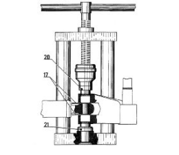
- Use the tool fitted with part 20 on its stem and part 21 on the tool base as shown in the figure.
- By moving the tool handgrip, push the two NADELLA bushings until their internal bottoms make contact with the pin end.
- Use the tool fitted with parts 3 and 4 to fit the pin, and press moving the tool handgrip, until wedging the washers on the swinging hub.
- Now, remove the two spacers (parts 17 and 16) and, once the space between the NADELLAs - steering tube and swinging hub - has been fully filled with grease, move the dust gaiter rings until they are placed in that space.
- By wedging the washers as described above, the front suspension unit refitting stage is finished.
Recommended products
AGIP GREASE MU3 Yellow-brown, lithium-base, medium-fibre multipurpose grease.
ISO L-X-BCHA 3 - DIN 51 825 K3K -20
Refitting
CAUTION
USE NEW ROLLER CASINGS, PIN, SEALING RINGS AND DUST GUARDS FOR REFITTING.
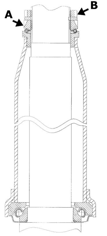
When fitting the fork, lubricate with the steering bearing tracks with the recommended grease.
Tighten the lower ring nut "A" and the upper ring nut "B" to the specified torque
Recommended products
AGIP GREASE PV2 Ivory smooth-textured, slightly-stringy anhydrous calcium-base
grease.
TL 9150 066, symbol NATO G 460
Locking torques (N*m)
Lower steering ring nut 8 ÷ 10 Upper steering ring nut 35 - 40
See also:
 Vespa Primavera 50 - Service manual > Front
Removing the front wheel Support the vehicle adequately. Loosen the five screws fixing the wheel to the hub.
Vespa Primavera 50 - Service manual > Front shock absorber
Removal Unscrew the fixing screw of the shock absorber cover and remove the plastic by unscrewing it downwards. Remove the swinging hub cover by disengaging the fittings. Support the vehicle adequately. Remove the wheel hub. Remove the seeger indicated in the photograph. Unscrew and remove the shock absorber lower retainer. Remove the brake calliper shock absorber support. Remove the two upper fixing screws. Remove the front shock absorber.
 BMW R 1250 RT
 Kymco Agility 50
 Piaggio Liberty 50
 Yamaha aerox NS50
 Aprilia SR50R
 Kymco Agility 50
 Vespa Primavera 50
 Peugeot Speedfight