 Vespa Primavera 50 - Service manual > Braking system
N.B.
THE UNITS OF MEASUREMENT CONTAINED IN THIS CHAPTER ARE EXPRESSED IN TERMS OF THE DECIMAL METRIC SYSTEM. TO REFER TO THE UNIT OF MEASUREMENT EXPRESSED IN TERMS OF THE ANGLO-SAXON SYSTEM, SEE THE "CHARACTERISTICS" CHAPTER.
Front brake calliper
Removal
- Adequately support the vehicle and remove the front wheel.
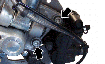
- Undo the screws indicated.
N.B.
SHOULD IT BE NECESSARY TO REPLACE THE CALLIPER, FIRST LOOSEN THE FITTING CONNECTING THE PIPE TO THE BRAKE CALLIPER.
Refitting
- To fit the calliper, follow the above operations but in reverse order.
Locking torques (N*m)
Screw tightening calliper to support 20 - 25
- If the calliper was replaced, bleed the system.
CAUTION
ALWAYS USE NEW COPPER WASHERS.
CAUTION
ONCE REFITTING IS FINISHED, BLEED THE SYSTEM.
Locking torques (N*m)
Brake fluid pipe-calliper fitting 20 - 25
Front brake disc
Removal
- Remove the front wheel
- Remove the front brake calliper
- Remove the hub and the disc operating on the wheel axle nut
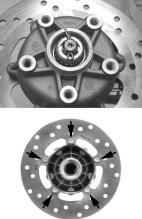
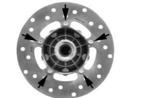
- Adequately support the hub with the disc and operating on the five screws shown in the photograph, remove the brake disc
Refitting
- Carry out the operations in the reverse order from the removal being careful to respect the direction of disc rotation shown by the arrow printed on it
- Tighten the 5 screws to the specified torque
Locking torques (N*m)
Brake disc screws: 6 +0.5 -1 Nm
Disc Inspection
- Remove the front wheel
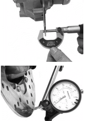
- Use a micrometer to check the disc thickness as shown in the photograph
- Repeat the measurement in at least 6 points on the disk
- Remove the front brake calliper
- In order to secure the appropriate tool adequately use a metal plate with M8 threaded hole and fix it to one of the two front brake calliper attachment points
- Place the dial gauge on the disk outer edge
- Make the wheel hub turn and check the disk deviation
Specific tooling
020335Y Dial gauge magnetic support
Characteristic
Standard thickness:
4 +0.2-0.2 mm
Max. deviation allowed:
0.1 mm
Front brake pads
Removal
- Remove the brake calliper.
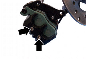
- Undo the indicated screws and remove the brake pads.
Refitting
- Follow the process in reverse order to refit.
Fill
Front
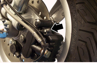
- Remove the rubber cap from the bleed screw.
- Insert a rubber pipe in the bleed screw to permit the brake fluid to be recovered.
- With the right-hand brake lever, load the system and bring it up to the required pressure.
- Keeping the right-hand brake lever pulled, loosen the bleed screw to purge the air. Then tighten the bleed screw
- Release the brake lever
- Repeat the operation until only brake fluid comes out of the rubber pipe.
- Remove the fluid recovery pipe and refit the rubber cap over the bleed screw.
- Top up the brake fluid to the right level in the reservoir.
If necessary, bleeding can be done using a special vacuum pump
N.B.
DURING THE BLEEDING OPERATIONS FREQUENTLY CHECK THE LEVEL TO PREVENT AIR GETTING INTO THE SYSTEM THROUGH THE PUMP.
N.B.
DURING THE BLEEDING OPERATIONS, MAKE SURE THE BRAKE FLUID DOES NOT COME INTO CONTACT WITH THE BODYWORK SO AS NOT TO DAMAGE IT. FURTHERMORE, DURING THE BLEEDING OPERATIONS REGARDING THE BRAKE CALLIPERS, MAKE SURE THE BRAKE FLUID DOES NOT COME INTO CONTACT WITH THE DISC BRAKES AND WITH THE BRAKE PADS. FAILURE TO OBSERVE THIS PRECAUTION WILL ENDANGER THE PROPER WORKING AND EFFICIENCY OF THE BRAKING SYSTEM
Specific tooling
020329Y Vacuum pump Mity-Vac
Locking torques (N*m)
System bleed calliper fitting: 20 to 25 Nm
Brake fluid level check
- Rest the vehicle on its centre stand on flat ground.
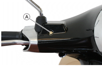
- The brake fluid reservoir has a sight glass "A" made of transparent material; the quantity of liquid contained in the sight glass indicates the level of fluid in the reservoir.
- When the sight glass "A" is full, the level inside the reservoir is above the MIN level; when it is partially full, the level has dropped to the MIN level; when it is fully empty, the level of fluid in the reservoir is below the MIN level.
N.B.
THE LEVEL TENDS TO DROP AS THE BRAKE PADS GET WORN, A MINIMUM LEVEL SHOULD NOT BE REACHED.
IF THE LEVEL IS TOO LOW, CHECK AND FIX THE SYSTEM SEALS, IF REQUIRED. TOP UP THE PUMP RESERVOIR, IF REQUIRED, CONSIDERING THAT THE "MAX." LEVEL MUST ONLY BE OBTAINED WITH NEW PADS.
- Under standard climatic conditions, replace fluid as indicated in the scheduled maintenance table.
Front brake pump
Removal
- Remove the upper handlebar cover
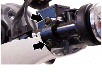
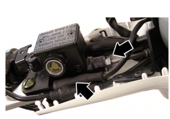
- Remove the two screws fixing the brake pump to the handlebar indicated in the photograph
- Remove the oil pipe joint from the pump
- Remove the connector from the stop lights switch
Refitting
For refitting, follow the operations in reverse order observing the tightening torque.
Locking torques (N*m)
Oil pipe joint to the pump: 20 - 25 Brake pump fixing screws to the handlebar: 7
to 10 Nm
Rear drum brake
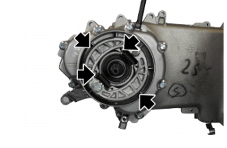
Once the silencer and the wheel have been removed, follow these steps:
1. Remove the shoe springs using the specific spanner.
2. Remove the shoe with the aid of a lever.
3. Refit the new shoes giving a few taps with the mallet.
4. Attach the springs using the specific pliers.
Specific tooling
020325Y Pliers for brake-shoe springs
See also:
 Vespa Primavera 50 - Service manual > Rear
Removing the rear wheel Remove the silencer. Remove the cotter pin and remove the cap. Unscrew the nut fixing the wheel axle and collect the washer.
 Vespa Primavera 50 - Service manual > Chassis
N.B. THE UNITS OF MEASUREMENT CONTAINED IN THIS CHAPTER ARE EXPRESSED IN TERMS OF THE DECIMAL METRIC SYSTEM. TO REFER TO THE UNIT OF MEASUREMENT EXPRESSED IN TERMS OF THE ANGLO-SAXON SYSTEM, SEE THE "CHARACTERISTICS" CHAPTER.
 BMW R 1250 RT
 Kymco Agility 50
 Piaggio Liberty 50
 Yamaha aerox NS50
 Aprilia SR50R
 Kymco Agility 50
 Vespa Primavera 50
 Peugeot Speedfight