 Vespa Primavera 50 - Service manual > Characteristics
Rules
This section describes general safety rules for any maintenance operations performed on the vehicle.
Safety rules
- If work can only be done on the vehicle with the engine running, make sure that the premises are well ventilated, using special extractors if necessary; never let the engine run in an enclosed area. Exhaust fumes are toxic.
- The battery electrolyte contains sulphuric acid. Protect your eyes, clothes and skin. Sulphuric acid is highly corrosive; in the event of contact with your eyes or skin, rinse thoroughly with abundant water and seek immediate medical attention.
- The battery produces hydrogen, a gas that can be highly explosive. Do not smoke and avoid sparks or flames near the battery, especially when charging it.
- Fuel is highly flammable and it can be explosive given some conditions. Do not smoke in the working area, and avoid naked flames or sparks.
- Clean the brake pads in a well-ventilated area, directing the jet of compressed air in such a way that you do not breathe in the dust produced by the wear of the friction material. Even though the latter contains no asbestos, inhaling dust is harmful.
Maintenance rules
- Use original PIAGGIO spare parts and lubricants recommended by the Manufacturer. Non-original or non-conforming spares may damage the vehicle.
- Use only the appropriate tools designed for this vehicle.
- Always use new gaskets, sealing rings and split pins upon refitting.
- After removal, clean the components using non-flammable or low flash-point solvents. Lubricate all the work surfaces, except tapered couplings, before refitting these parts.
- After refitting, make sure that all the components have been installed correctly and work properly.
- Use only equipment with metric sizes for removal, service and reassembly operations. Metric bolts, nuts and screws are not interchangeable with coupling members using English measurements. Using unsuitable coupling members and tools may damage the vehicle.
- When carrying out maintenance operations on the vehicle that involve the electrical system, make sure the electrical connections have been made properly, particularly the ground and battery connections.
Vehicle identification
VEHICLE IDENTIFICATION 125

VEHICLE IDENTIFICATION 150

VEHICLE IDENTIFICATION USA-CND

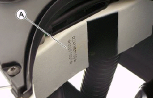
Chassis number
The chassis number "A" is stamped near the fuel tank.
To read it, proceed as follows:
- lift the saddle;
- lift the helmet compartment by removing it.
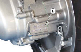
Engine number
The engine number "B" is stamped near the rear left shock absorber lower support.
Dimensions and mass
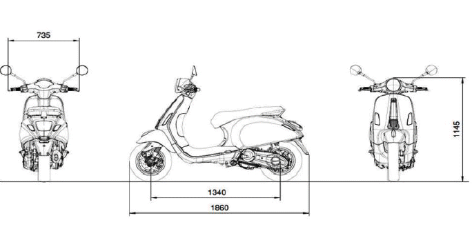
WEIGHT AND DIMENSIONS

Engine
125 CM³ ENGINE SPECIFICATIONS
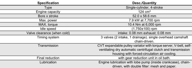

150 CM³ ENGINE SPECIFICATIONS
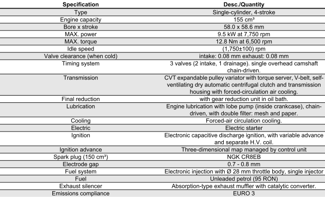
Transmission
TRANSMISSION

Capacities
CAPACITY

Frame and suspensions
FRAME AND SUSPENSION

Brakes
BRAKES

Wheels and tyres
WHEELS AND TYRES

Tightening Torques
FRAME ASSEMBLY

STEERING ASSEMBLY

FRONT BRAKE

(º) Apply LOCTITE 242 threadlock
SILENCER

FRONT SUSPENSION

(º) Apply LOCTITE 242 threadlock
REAR SUSPENSION

FLYWHEEL

FLYWHEEL COVER

CRANKCASE
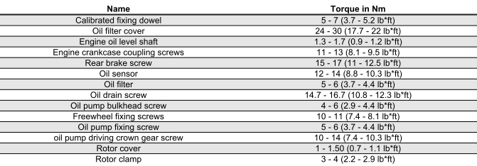
HEAD AND CYLINDER


TRANSMISSION AND FINAL REDUCTION

LUBRICATION

Overhaul data
Assembly clearances
Cylinder - piston assy.
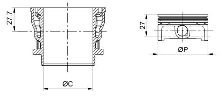
CYLINDER - PISTON (125)

CYLINDER - PISTON (150)

COUPLING CATEGORIES (125)

COUPLING CATEGORIES (150)

N.B.
THE PISTON MUST BE INSTALLED WITH THE ARROW FACING TOWARDS THE EXHAUST SIDE, THE PISTON RINGS MUST BE INSTALLED WITH THE WORD "TOP" OR THE STAMPED MARK FACING UPWARDS.
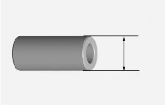
- Check the pin outside diameter
Characteristic
Pin outside diameter
14 (+0 -0.004) mm
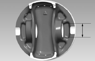
- Measure the diameter of the housings on the piston.
Characteristic
Standard diameter
14 (+0.006 +0.001) mm
- Carefully clean the sealing rings housings.
- Measure the sealing rings - pistons coupling clearance using suitable sensors, as shown in the diagram
- If clearances measured exceed the limits specified in the table below, the piston should be replaced by a new one.
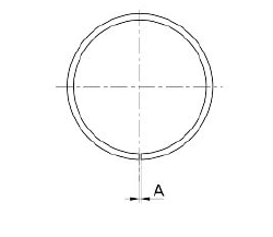
- Check the clearance upon mounting (A) of the bands:
N.B.
MEASURE CLEARANCE BY INSERTING THE BLADE OF THE FEELER GAUGE FROM THE 2nd SEALING RING SIDE.
ASSEMBLY CLEARANCE OF BANDS - SEAL RINGS (125)

ASSEMBLY CLEARANCE OF BANDS - SEAL RINGS (150)

- Check that the coupling surface with the head is not worn or misshapen.
- Pistons and cylinders are classified according to diameter. The coupling is carried out in pairs (A-A, B-B, C-C, D-D).
Crankcase - crankshaft - connecting rod
CRANKSHAFT

Axial clearance between crankshaft and connecting rod

CRANKSHAFT / CONNECTING ROD AXIAL CLEARANCE

Crankshaft bearing diameter.
Measure the bearings on both x-y axes.

CRANKSHAFT

- In order to obtain proper bushing lubrication, make sure there are both an outstanding lubrication pressure and a good oil flow rate. To that end, the bushings must be correctly positioned so as not to obstruct the oil supply channels.
Characteristic
"A"
AXIS CYLINDER
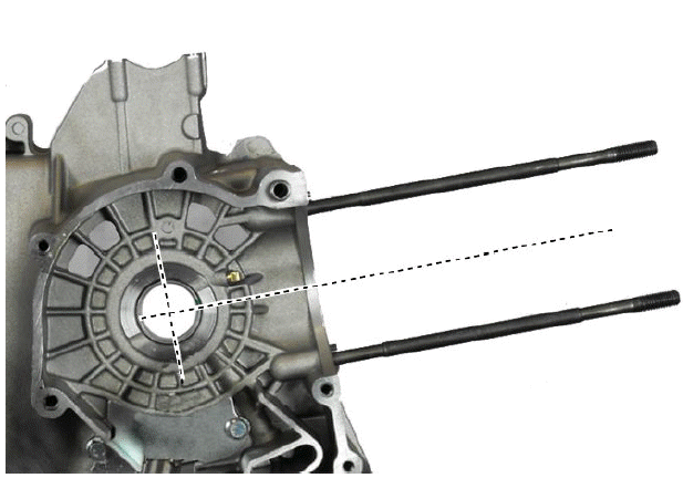
- The main bushings have 2 half-bearings, 1 with and 1 without the lubrication channel.
- The solid half-bearing is intended to stand the thrusts caused by combustion, and for this reason, it is arranged opposed to the cylinder.
- To prevent shutters in the oil feeding channels, the matching surface of the two half-bearings must be perfectly orthogonal to the cylinder axis, as shown in the photo.

Characteristic
"A"
AXIS CYLINDER
BUSHINGS

- The section of the oil feeding channels is also influenced by the driving depth of the bushings.
- Visually check the wear of the bushings: in the coupling ends shown in the photo the bushing usually keeps the original look, check in the rest of the bushing if there is evident removal of material. If this occurs as stated, proceed to replace the crankcase halves.

N.B.
SMALL MARKS AND SCRATCHES OF THE SHAFT ROTATION ARE NORMAL SIGNS OF ENGINE USAGE, AND DO NOT AFFECT THE CORRECT FUNCTIONING.
Measurement of crankcase halves - crankshaft coupling clearance.
- The nominal diameters of the bushings, even if of the same coupling category, may differ by hundredths due to the plastic slackening of the material of the crankcase due to the driving load.
- Measure along the axis of the " A" cylinder, using a bore meter at two depths indicated in the figure, the diameter of the bushings.
- After measuring the two diameters, take the average.
Characteristic
"A"
AXIS CYLINDER
- The bushings housing hole in the crankcase half is divided into two categories depending on the size, Category 1 and Category 2.
CRANKCASE DIAMETER WITHOUT BUSHING

- Combine the shaft with two category 1 crankwebs with the category 1 crankcase (or cat. 2 with cat. 2). Furthermore a spare crankcase cannot be matched with a crankshaft with mixed categories. The spare crankshaft has half-shafts of the same category.
- According to the classification of the shaft CAT.1 - CAT.2 combine a complete crankcase pre-fitted with suitable bushings according to the starting shaft.
CATEGORIES

THE CRANKSHAFT is available in two CATEGORIES:
Characteristic
Crankshaft category:
CAT. 1 - CAT. 2
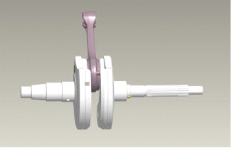
CRANKSHAFT CATEGORY IDENTIFICATION:
The identification is indicated on the counterweight shoulder "*1 - *2", if carried out with micropinholing.
Otherwise, "1 - 2" if done manually with an electric pen. The spare part identification is located on the package with a drawing number plus FC1/FC2 or (001/002).
If a crankshaft comprising two half-shafts of different categories needs to be replaced, also replace both crankcase halves, combining the two components (Shaft and Crankcase) featuring the same category.
Cylinder Head
Clean all the coupling surfaces thoroughly before servicing the head. Pay attention to the position of the springs and valves so as not to change the original position upon refitting them
- Using a trued bar and a thickness gauge, check that the cylinder head surface is not worn or distorted.
Characteristic
Maximum run-out allowed:
0.03 mm
- In case of irregularities, replace the head.
- Check the sealing surfaces for the exhaust manifold.
- Check that the camshaft and the rocker pin bearings show no signs of wear.
- Check that the head cover show no signs of wear.
- Check that there is no cooling liquid leakage from the seals.
- Fit the valves into the cylinder head.
- Alternatively test the intake and exhaust valves.
- The test should be carried out by filling the manifold with fuel and checking that the head does not ooze through the valves when they are just pressed by the fingers.
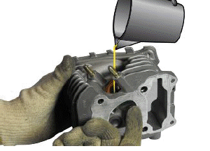
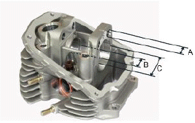
HEAD BEARINGS

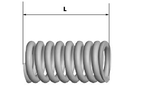
Measure the unloaded spring length
Characteristic
Standard length
35.8 mm
- Remove any carbon deposits from the valve seats.
- Check the width of the mark on the valve seat "V" with Prussian blue.
Characteristic
Standard value:
1 - 1.3 mm
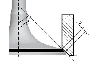
- If the width of the mark on the valve seat is larger than the prescribed limits, true the seats with a 45º milling cutter and then grind.
- Replace the head in case of excessive wear or damage.
- Measure the diameter of the valve stem at the three positions indicated in the diagram.
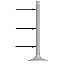
STANDARD DIAMETER

- Calculate the clearance between the valve and its guide.
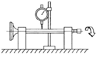
- Check the deviation of the valve stem by resting it on a "V" shaped support and measuring the extent of the deformation using a dial gauge.
Characteristic
Limit value allowed:
0.02 mm
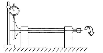
- Check the oscillation of the valve head by arranging a dial gauge at right angle relative to the valve head and rotate it on a "V" shaped abutment.
Characteristic
Limit allowed:
0.3 mm
Measure the valve guides.
Characteristic
Valve guide:
4.3 +- 0.1 mm
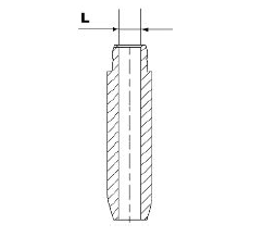
- After measuring the valve guide diameter and the valve stem diameter, check the clearance between guide and stem.

INTAKE

EXHAUST

- Check that there are no signs of wear on the faying surface with the set screw articulated terminal.
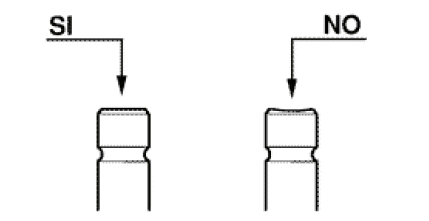
- If no faults are found during the above checks, the same valves can be
reused. For better sealing results, we recommend grinding the valve seats.
Grind the valves gently with fine-grained lapping compound.
Upon grinding, keep the cylinder head in horizontal position. This will prevent the lapping compound residues from penetrating between the valve stem and the guide (see figure).
CAUTION
TO AVOID SCORING THE FAYING SURFACE, DO NOT ROTATE THE VALVE WHEN NO LAPPING COMPOUND IS LEFT. CAREFULLY WASH THE CYLINDER HEAD AND THE VALVES WITH A SUITABLE PRODUCT FOR THE TYPE OF LAPPING COMPOUND BEING USED.
CAUTION
DO NOT CHANGE THE VALVE FITTING POSITION (RH - LH).
- Check the camshaft bearings for signs of abnormal wear or scores.
- Using a micrometer, measure the camshaft bearings.
STANDARD DIAMETER


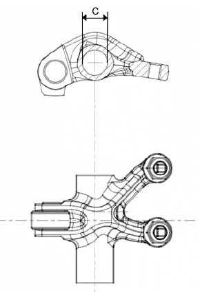
- Check the outside diameter of the rocker pins
- Check there are no signs of wear or scoring on the rocker pins.
- Check the internal diameter of each rocker arm.
- Check there are no signs of wear on the contact pads with the cam and on the jointed adjustment plate.
DIAMETER OF PINS AND ROCKING LEVERS


Slot packing system
Characteristic
Compression ratio
(10.5+-0.5):1
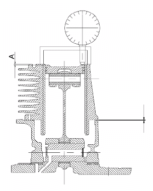
Distance "A" to be measured is a value of piston recess, it indicates by how much the piston crown descends below the plane formed by the cylinder crown. The further the piston enters into the cylinder, the thinner the base gasket to be used should be (to compensate the compression ratio) and vice versa.
N.B.
DISTANCE "A" SHOULD BE MEASURED WITH NO GASKET FITTED BETWEEN THE CRANKCASE AND THE CYLINDER AND AFTER RESETTING THE DIAL GAUGE, WITH SUPPORT, ON A GROUND PLANE
ENGINE 125/150 SHIMMING

Products
RECOMMENDED PRODUCTS TABLE

UNIT OF MEASURE - CONVERSION - ENGLISH SYSTEM TO INTERNATIONAL SYSTEM (IS).

Tooling
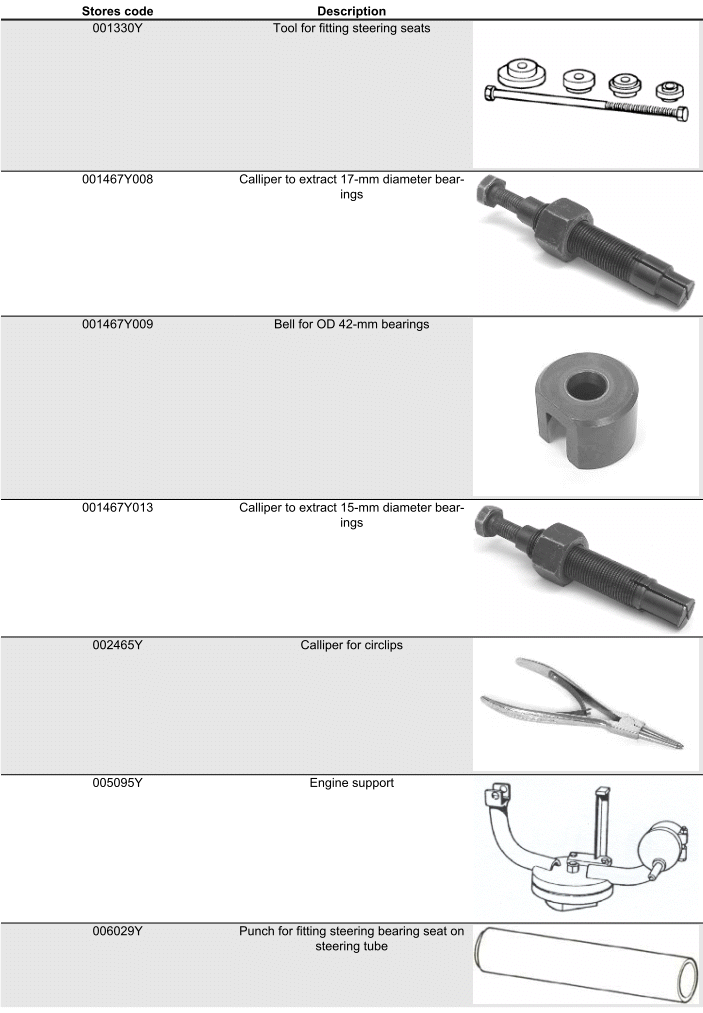
SPECIFIC TOOLS
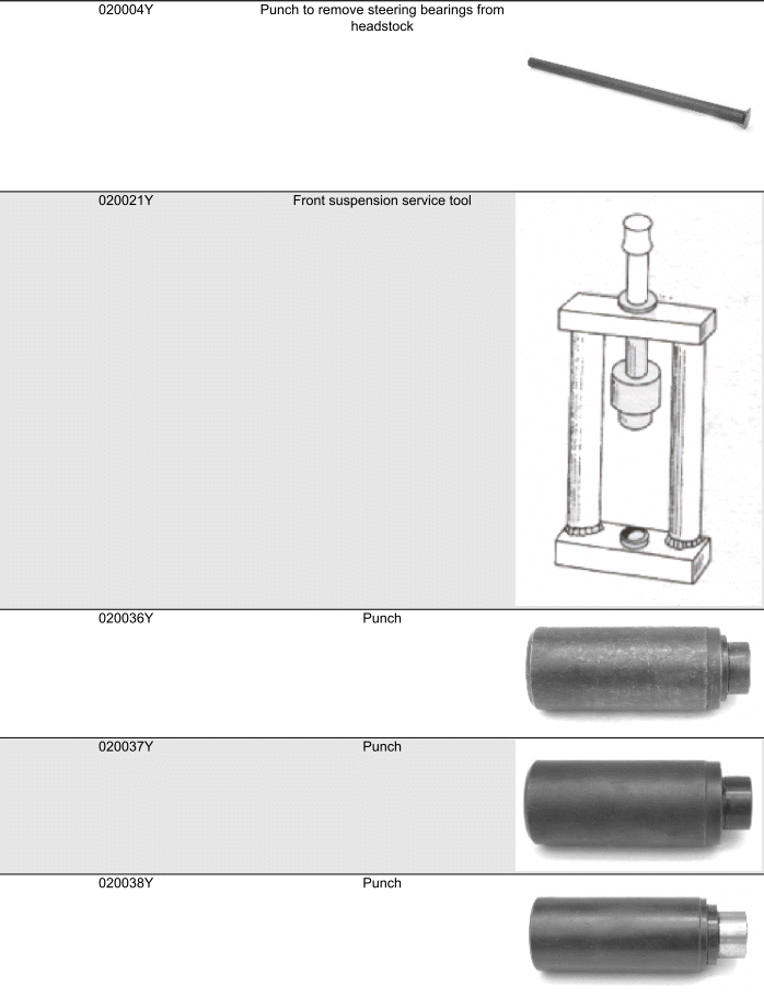
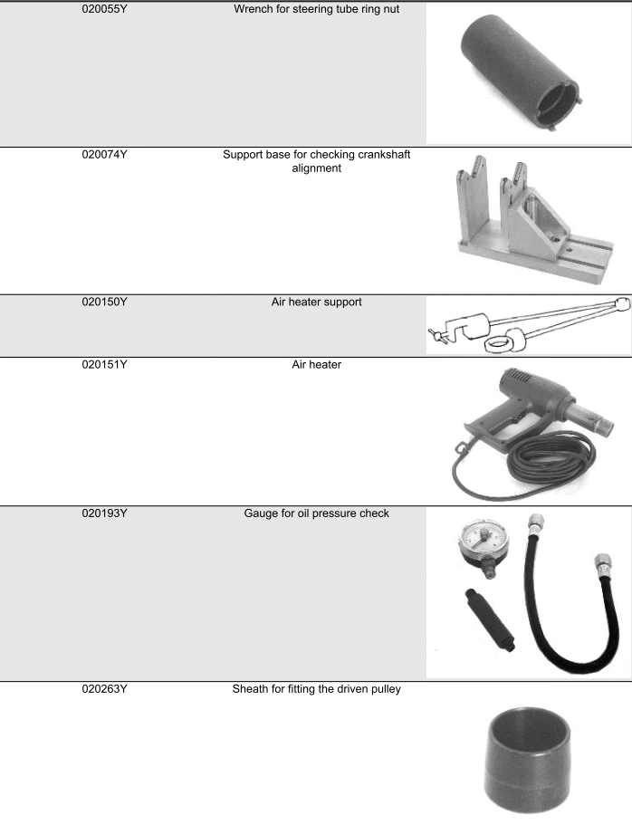
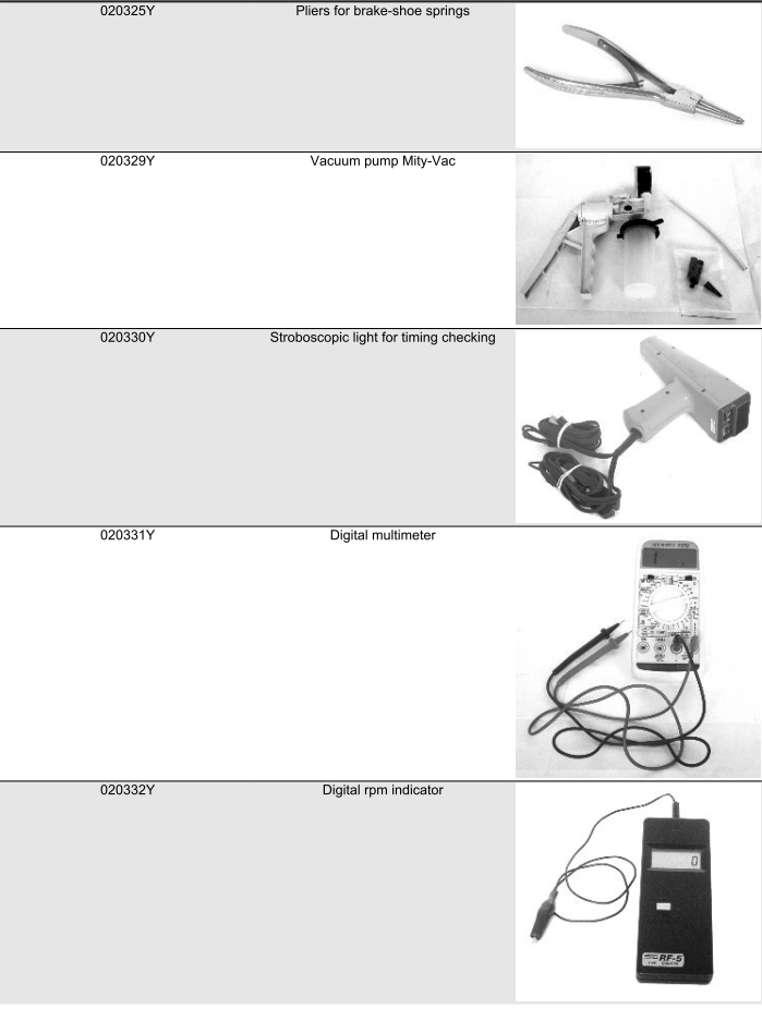
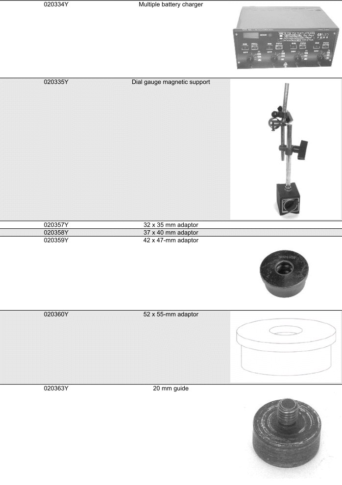
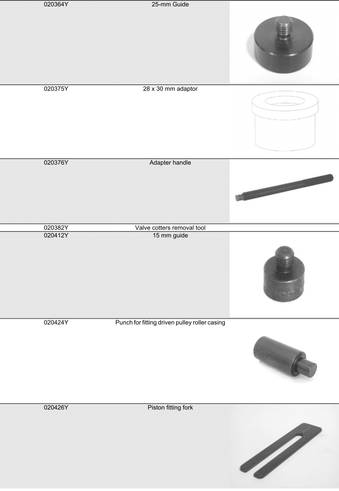
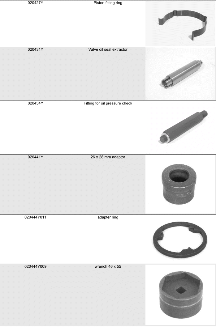
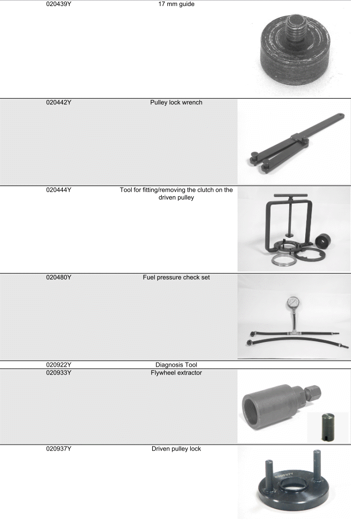
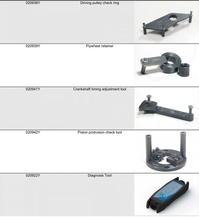
See also:
 Vespa Primavera 50 - Service manual > Maintenance
N.B. THE UNITS OF MEASUREMENT CONTAINED IN THIS CHAPTER ARE EXPRESSED IN TERMS OF THE DECIMAL METRIC SYSTEM. TO REFER TO THE UNIT OF MEASUREMENT EXPRESSED IN TERMS OF THE ANGLO-SAXON SYSTEM, SEE THE "CHARACTERISTICS" CHAPTER.
 BMW R 1250 RT
 Kymco Agility 50
 Piaggio Liberty 50
 Yamaha aerox NS50
 Aprilia SR50R
 Kymco Agility 50
 Vespa Primavera 50
 Peugeot Speedfight