 Kymco Agility 50 - Service manual > Charging system
SHORT CIRCUIT TEST
Disconnect the ground wire from the battery and connect an ammeter across the battery negative (-) terminal and the ground wire.
Turn the ignition switch OFF and check for short circuit.
Connect the electric tester positive (+) terminal to ground wire and the tester negative (-) terminal to the battery negative (-) terminal.
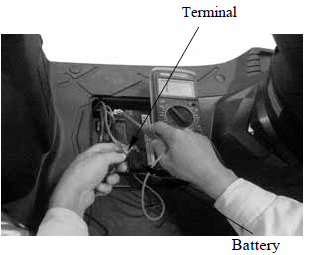
If any abnormality is found, check the ignition switch and wire harness for short circuit .
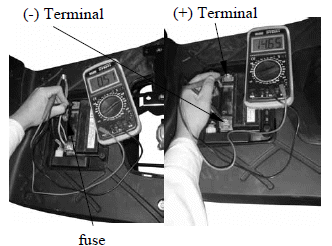
CURRENT TEST
This inspection must be performed with an electric tester when the battery is fully charged.
Warm up the engine for inspection.
Connect the electric tester across the battery terminals. Disconnect the fuse and connect an ammeter between the fuse terminals.
Attach a tachometer to the engine.
Start the engine and gradually increase the engine speed to measure the limit voltage and current.
Limit Voltage/Current: 14~15V/0.5A max. (5000rpm max.)
If the limit voltage is not within the specified range, check the regulator/rectifier.
LIGHTING SYSTEM LIMIT VOLTAGE INSPECTION
Remove the handlebar front cover.
Measure the voltage with the electric tester in the AC range.
Limit Voltage: 12~14V/ (5000rpm max.)
If the limit voltage is not within the specified range, check the regulator/rectifier.
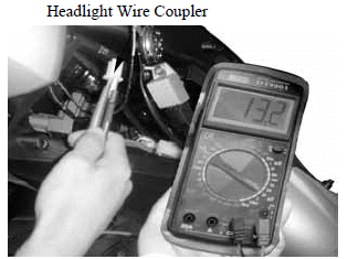
Perform this test with a fully charged battery.
REGULATOR/RECTIFIER
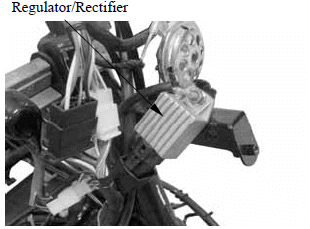
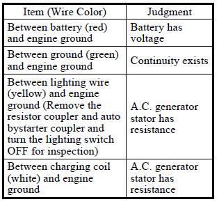
MAIN HARNESS CIRCUIT INSPECTION
Remove the front covers. Remove the regulator/rectifier 4P coupler and check for continuity between the wire harness terminals according to the following :
REGULATOR/RECTIFIER INSPECTION
If the main harness terminals are normal, check the regulator/rectifier coupler for loose connection and measure the resistances between the regulator/rectifier terminals.
- Do not touch the tester probes with your finger because human body has resistance.
- Use the following specified testers for accurate testing. Use of an
improper tester in an improper range may give false readings.
- Kowa Electric Tester
- Sanwa Electric Tester
- Kowa Electric Tester TH-5H
- Proper range for testing:
- Use XK
 range for Sanwa Tester
 - Use X100
range for Kowa Tester
- Use XK
- If the dry battery in the tester is weak, the readings will be incorrect. In this case, check the dry battery.
- The Kowa tester readings are 100 times the actual values. Be careful during testing.
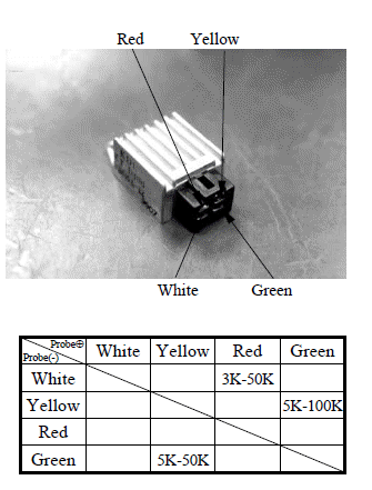
Replace the regulator/rectifier if the readings are not within the specifications in the table.
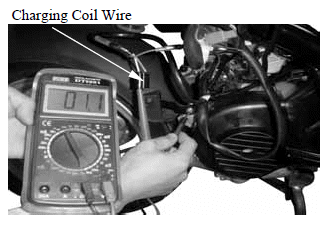
A.C. GENERATOR CHARGING COIL
The inspection of A.C. generator charging coil can be made with the engine installed.
INSPECTION
Disconnect the A.C. generator 2P connector.
Measure the resistance between the A.C.
generator white wire and engine ground with an electric tester.
Standard: 0.2-1.2(at 20)
Replace the A.C. generator charging coil if the reading is not within the specifications.
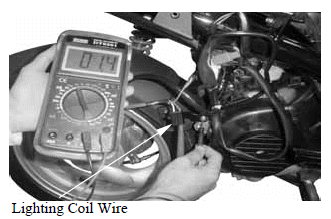
A.C. GENERATOR LIGHTING COIL
The inspection of A.C. generator lighting coil can be made with the engine installed.
INSPECTION
Disconnect the A.C. generator 2P connector.
Measure the resistance between the A.C.
generator yellow wire and engine ground with an electric tester.
Standard: 0.1-1.0 (20)
Replace the A.C. generator lighting coil if the reading is not within the specifications.
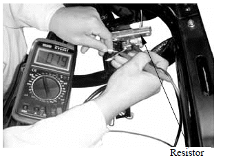
RESISTOR INSPECTION
Remove the front covers.
Measure the resistance between the resistor lead and engine ground.
Resistances:
5W12: 11-13
30W7.5: 6-8
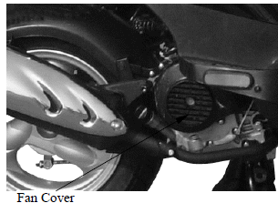
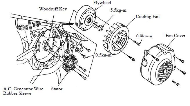
A.C. GENERATOR REMOVAL
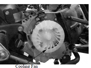
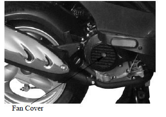
Remove the right side cover. Remove the four bolts attaching the cooling fan cover to remove the fan cover.
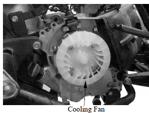
Remove the cooling fan by removing the four cooling fan attaching bolts.
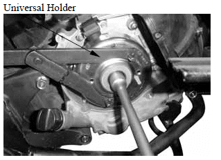
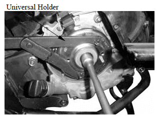
Hold the flywheel with an universal holder.
Remove the flywheel nut.

Universal Holder
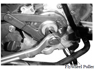
Remove the A.C. generator flywheel using the flywheel puller.
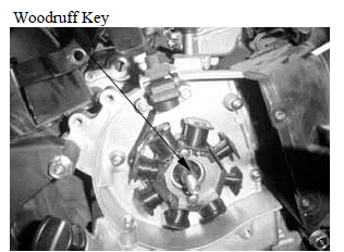
Remove the woodruff key.

Flywheel Puller
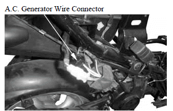
Remove the A.C. generator wire connector.
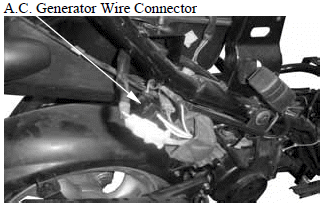
Remove the A.C. generator wire set plate.
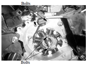
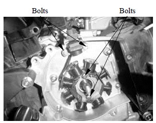
Remove the pulser coil bolts.
Remove the A.C. generator wire rubber sleeve and pulser coil from the right crankcase.
Remove the two bolts and A.C. generator stator.
A.C. GENERATOR INSTALLATION
Install the A.C. generator stator and pulser coil onto the right crankcase.
Tighten the stator and pulser coil bolts.
Torques:
Pulser Coil : 0.45~0.6kgf-m
Stator : 0.8~1.2kgf-m
Install the A.C. generator wire rubber sleeve and A.C. generator wire set plate.
Connect the A.C. generator wire connector.
Clean the taper hole in the flywheel off any burrs and dirt.
Install the woodruff key in the crankshaft keyway.
Install the flywheel onto the crankshaft with the flywheel hole aligned with the crankshaft woodruff key.
The inside of the flywheel is magnetic.
Make sure that there is no bolt or nut before installation.
Hold the flywheel with the universal holder and tighten the flywheel nut.
Torque: 3.5~4.5kgf-m

Universal Holder
Install the cooling fan.
Torque: 0.8~1.2kgf-m
Install the fan cover.
Install the right side cover.
See also:
 Kymco Agility 50 - Service manual > Battery
REMOVAL Remove the battery cover screws on the floor board. Open the battery cover and remove the battery by removing the bolt and band. First disconnect the battery negative (-) cable and then the positive (+) cable.
Kymco Agility 50 - Service manual > Ignition System
CDI Unit Ignition Switch A.C. Generator Pulser Coil Spark Plug
 BMW R 1250 RT
 Kymco Agility 50
 Piaggio Liberty 50
 Yamaha aerox NS50
 Aprilia SR50R
 Kymco Agility 50
 Vespa Primavera 50
 Peugeot Speedfight