 Vespa Primavera 50 - Service manual > Crankcase - crankshaft
Splitting the crankcase halves
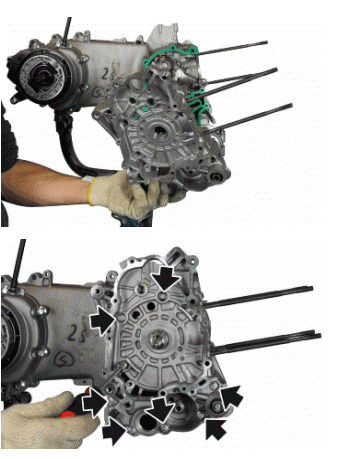
- Undo the eight crankcase coupling screws.
- Separate the crankcase halves while keeping the crankshaft in one of these two halves.
- Only after the halves have been separated, can the crankshaft be checked.
CAUTION
WHILE OPENING THE CRANKCASES AND REMOVING THE CRANKSHAFT, CHECK THAT THE THREADED SHAFT ENDS DO NOT INTERFERE WITH THE MAIN BUSHINGS.
FAILURE TO OBSERVE THIS PRECAUTION CAN DAMAGE THE MAIN BUSHINGS.
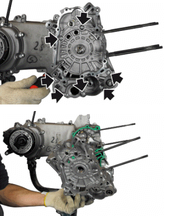
- Remove the gasket and be careful with the alignment dowels.
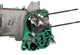
Inspecting the crankshaft components
N.B.
TO MEASURE WEAR LIMITS AND COUPLING CLEARANCES, SEE THE SPECIFICATIONS CHAPTER.
Inspecting the crankshaft alignment
N.B.
TO MEASURE WEAR LIMITS AND COUPLING CLEARANCES, SEE THE SPECIFICATIONS CHAPTER.
Inspecting the crankcase halves
- Before proceeding to check the crankcase halves, thoroughly clean all surfaces and oil ducts.
- On the transmission-side crankcase half, take particular care when handling the oil pump compartment and the oil ducts, the by-pass duct, the main bushings and the cooling jet on the transmission side.
- Take particular care, also, that there are no signs wear in the oil by-pass valve housing (see Chapter Lubrication), as this could prevent a good seal in the piston, which regulates the oil pressure.
- On the flywheel side crankcase half, take particular care cleaning the oil ducts for the main bushings, the oil duct for the jet that lubricates the cylinder head and the oil drainage duct at the flywheel side oil seal.
- Inspect the coupling surfaces on the crankcase halves for scratches or deformation, taking particular care with the cylinder/crankcase surfaces and the crankcase halves surfaces.
- Defects in the crankcase coupling gasket between the crankcase halves or the mating surfaces shown in the diagram, could cause a drop in the oil pressure lubricating the main bushings and connecting rod.
- Check the main bearing seats that limit axial clearance in the crankshaft show no signs of wear. The dimension between these seats is measured by way of the procedure described previously for measuring the crankshaft axial clearance and dimensions.
N.B.
THE JET IS FED THROUGH THE MAIN BUSHINGS. PROPER OPERATION OF THIS COMPONENT IMPROVES PISTON CROWN COOLING. CLOGGING HAS EFFECTS THAT ARE DIFFICULT TO DETECT (PISTON TEMPERATURE INCREASE). FAILURE OR LEAKS CAN CAUSE A CONSIDERABLE DROP IN THE LUBRICATION PRESSURE FOR MAIN BUSHINGS AND CONNECTING ROD.
N.B.
THE HEAD LUBRICATION CHANNEL IS PROVIDED WITH A SHUTTER JET; THIS GIVES A "LOW PRESSURE" HEAD LUBRICATION; THIS CHOICE WAS MADE TO REDUCE THE OIL TEMPERATURE IN THE SUMP. THE JET CLOGGING IMPAIRS THE HEAD LUBRICATION AND THE TIMING MECHANISMS. A JET FAILURE CAUSES A DECREASE OF THE MAIN BUSHING AND CONNECTING ROD LUBRICATION PRESSURE.
Inspecting the crankshaft plain bearings
- To obtain a good bushing lubrication it is necessary to have both an optimal lubricating pressure (3.2 bar) and a good oil flow rate; the bushings must be correctly positioned so as not to obstruct the oil supply channels.
- The main bushings are comprised of 2 half-bearings, one with holes and channels for lubrication while the other is solid.
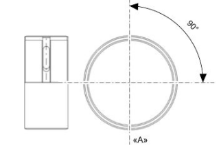
Characteristic
"A"
AXIS CYLINDER
- The oil feeding channel section is also affected by the bushings driving depth compared with the crankshaft axial clearance of the limiting surface.
N.B.
TO MEASURE WEAR LIMITS AND COUPLING CLEARANCES, SEE THE SPECIFICATIONS CHAPTER.
Coupling chart
N.B.
TO MEASURE WEAR LIMITS AND COUPLING CLEARANCES, SEE THE SPECIFICATIONS CHAPTER.
Refitting the crankcase halves
- Follow the removal steps but in reverse order; be careful to respect the prescribed tightening torques.
- Insert the by-pass.
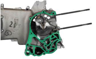
- Insert a new gasket and be careful with the alignment dowels.
- Maintaining the crankshaft inserted in the flywheel side crankcase, couple the crankcase halves.
- Insert the screws and tighten to specified torque.
CAUTION
CAREFULLY CHECK THE CLEANING OF THE BY-PASS DUCT.
CHECK THAT THE PISTON SLIDES BY HAND, FREELY AND WITHOUT STICKING.
CAUTION
IT IS ADVISABLE TO INSERT THE CRANKSHAFT IN THE FLYWHEEL SIDE CRANKCASE HALF TO PREVENT, WITH ACCIDENTAL MOVEMENTS DURING INSERTION, THE OIL PUMP CONTROL TOOTHING FROM DAMAGING THE BUSHINGS.
Locking torques (N*m)
Engine crankcase coupling screws 11 - 13
- Complete the coupling operations with the verification of the crankshaft axial clearance.
- Using specific tools to support the dial gauge, verify that the fitting clearance is within the limits.
- Higher clearances are signs of wear of the crankshaft - crankcase supporting surfaces.
Characteristic
Crankshaft-crankcase axial clearance
0.2 to 0.5 mm
Studs
- Using two nuts, fitted as nut and lock nut type, remove and then drive from the seat.
- Proceed with a thorough cleaning of the threaded seat on the crankcase.
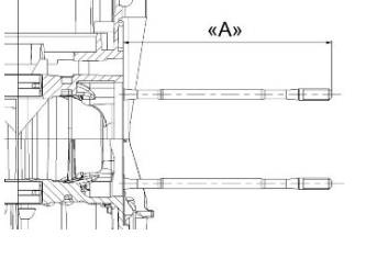
- Screw the new stud bolts up to the driving depth indicated.
N.B.
NEW STUD BOLTS DO NOT NEED THREADLOCK, AS THEY COME EQUIPPED WITH SCOTCH-GRIP.
Characteristic
Driving depth of stud bolts "A"
170 mm+ 0.5
See also:
 Vespa Primavera 50 - Service manual > Cylinder assy. and timing system
Removing the intake manifold The intake manifold is positioned on the head, loosen the clamps and remove the sleeve connecting to the throttle body. Undo the three manifold fixing screws and remove it.
 Vespa Primavera 50 - Service manual > Lubrication
Conceptual diagrams The lobe pump "F" sucks the oil from the sump, through the mesh pre-filter "C", it pushes it into the cartridge filter "E" where there is also a safety valve "D".
 BMW R 1250 RT
 Kymco Agility 50
 Piaggio Liberty 50
 Yamaha aerox NS50
 Aprilia SR50R
 Kymco Agility 50
 Vespa Primavera 50
 Peugeot Speedfight