 Vespa Primavera 50 - Service manual > Cylinder assy. and timing system
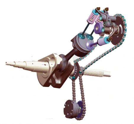
Removing the intake manifold
- The intake manifold is positioned on the head, loosen the clamps and remove the sleeve connecting to the throttle body.
- Undo the three manifold fixing screws and remove it.
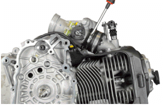
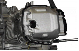
Removing the rocker-arms cover
- Remove the protective cover, undoing the three screws.
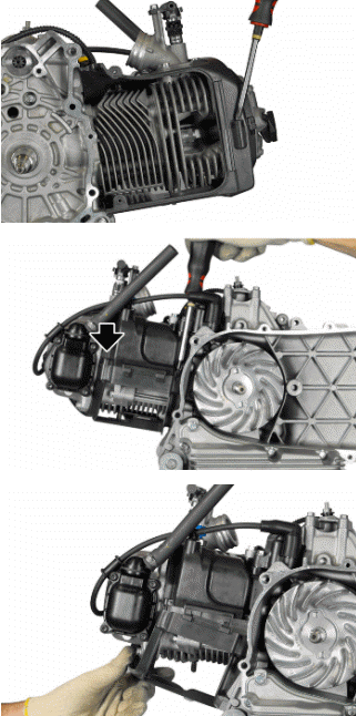
- Remove the engine temperature sensor.
- Undo the screw indicated.
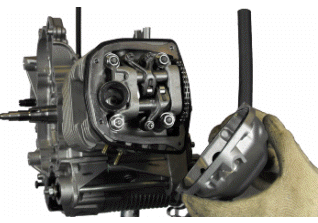
- Remove the upper part of the cover.
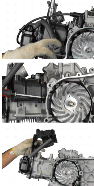
- Unscrew the four screws and remove the tappet cover.
Removing the timing system drive
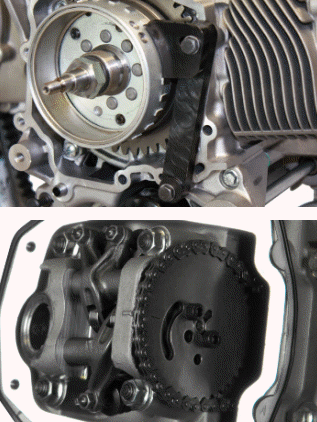
- Before carrying out operations on the timing system we recommend positioning the engine at TDC in compression. To do this use the specific tools.
- Use the holes on the engine crankcase to secure the tool.
- Position the specific tool in the window between the flywheel pick-up references as illustrated in the figure.
Specific tooling
020941Y Crankshaft timing adjustment tool
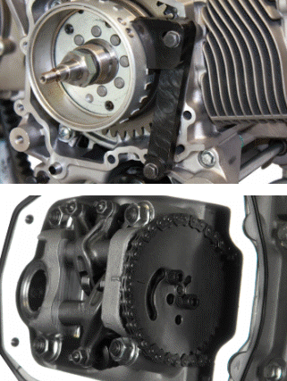
- First loosen the tensioner and unscrew the fixing screws.
- Remove the tensioner complete with gasket.
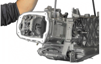
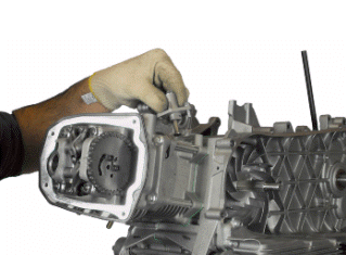
- Undo the two screws on the timing system gear.
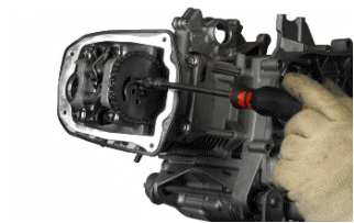
- Disengage the timing system gear and remove the camshaft control sprocket.
- Remove the cylinder as described in section "Engine/Piston cylinder disassembly"
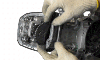
After removing the head the camshaft control components can be removed:
- Remove the inspection cover as described in sec.
"Lubrication/Main bushing oil seals removal".
- Remove the oil pump command as described in section "Lubrication/Oil pump/Disassembly ".
- Undo the chain tensioner pad fixing screw, remove the bushing and the slider.
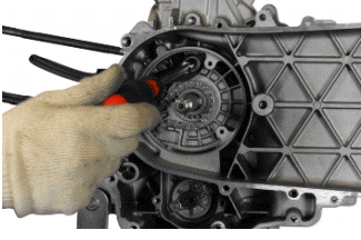
- Remove the chain tensioner pad.
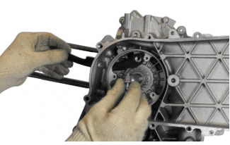
- Remove the control gear.
- Remove the seal OR.
- Remove the flat washer.
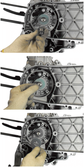
CAUTION
REMEMBER TO CORRECTLY POSITION THE SEAL OR IN THE REFITTING PHASE.
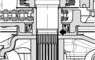
- Release the timing chain from the crankshaft
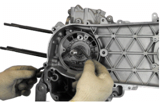
- Remove the control gear.
Removing the cam shaft
- Undo the camshaft lock screw.
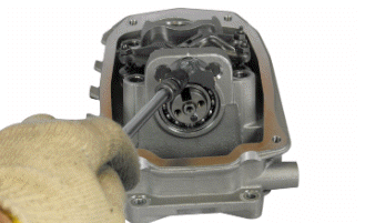
- Remove the lock.
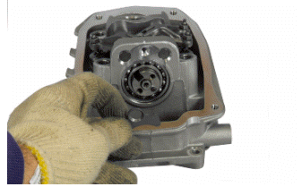
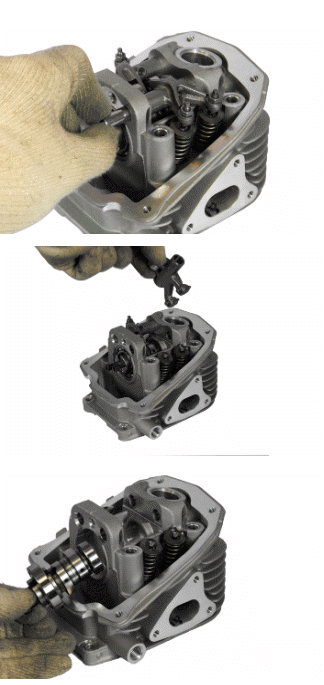
- Remove the two pins and the rockers.
- Remove the camshaft.
Removing the cylinder head
- Gradually loosen the four screws in crossed sequence and recover the washers.
- Undo the two external screws.
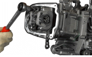
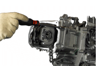
- Remove the cylinder head.
- Remove the chain guide slider and the gasket.
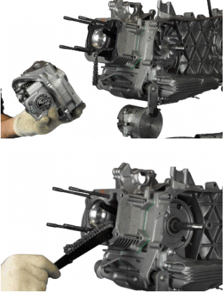
- Remove the gasket.
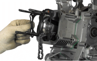
N.B.
ON ASSEMBLY PAY CLOSE ATTENTION TO THE TWO DOWELS.
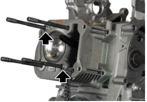
Removing the valves
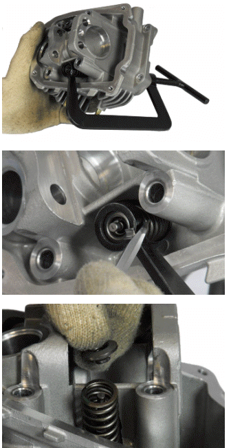
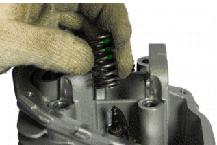
- Use the specific tool to remove the cotters, cap and spring.
CAUTION
PROPERLY REPLACE THE PADS AND ROCKERS SO AS TO PRESERVE THE COUPLINGS.
CAUTION
DURING ASSEMBLY, POSITION THE VALVE SPRINGS WITH THE GREEN COLOURED COIL FACING UPWARD.
Specific tooling
020382Y Valve fitting/ removal tool
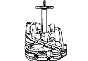
- Use the specific tool to remove the valve oil seal.
Specific tooling
020431Y Valve oil seal extractor
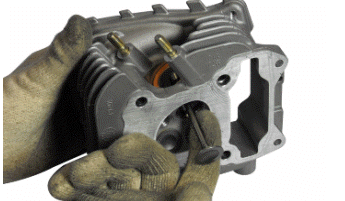
- Slide off the valve and remove the lower support.
Removing the cylinder - piston assy.
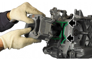
- Remove the cylinder, paying attention to the cylinder- crankcase alignment dowels.
CAUTION
TO AVOID DAMAGING THE PISTON, KEEP IT FIRM WHILE REMOVING THE CYLINDER.
N.B.
IN ORDER NOT TO DAMAGE THE BASE GASKET WITH THE PISTON LOCK FORK 020426Y DURING THE MOUNTING PHASE, IT IS RECOMMENDED TO INSERT THE ALIGNMENT DOWELS OF THE CYLINDER - CRANKCASE UNDER THE CYLINDER DURING THE ASSEMBLY.
- Remove the base gasket.
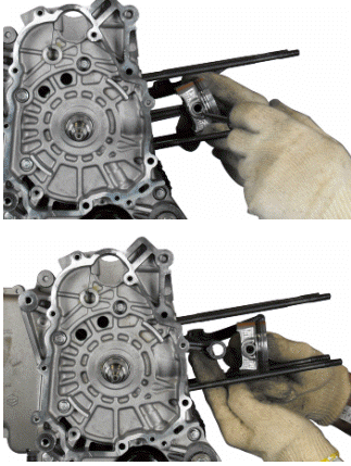
Remove the retainer rings and remove the piston.
N.B.
BE CAREFUL NOT TO DAMAGE THE SEALING RINGS DURING REMOVAL.
Inspecting the small end
N.B.
TO MEASURE WEAR LIMITS AND COUPLING CLEARANCES, SEE THE SPECIFICATIONS CHAPTER.
Inspecting the wrist pin
N.B.
TO MEASURE WEAR LIMITS AND COUPLING CLEARANCES, SEE THE SPECIFICATIONS CHAPTER.
Inspecting the piston
N.B.
TO MEASURE WEAR LIMITS AND COUPLING CLEARANCES, SEE THE SPECIFICATIONS CHAPTER.
Inspecting the piston rings
N.B.
TO MEASURE WEAR LIMITS AND COUPLING CLEARANCES, SEE THE SPECIFICATIONS CHAPTER.
Removing the piston
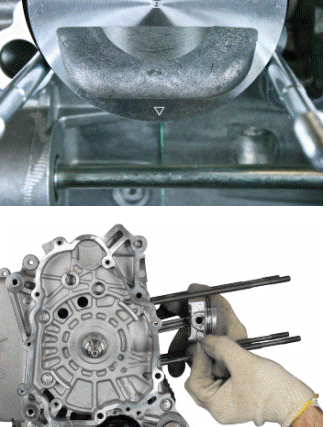
- Fit the piston and pin onto the connecting rod, aligning the piston arrow towards the engine direction of rotation.
CAUTION
AT EVERY NEW MOUNTING USE RETAINER RING PINS.
Choosing the gasket
- First fit the piston into the cylinder, without any base gasket.
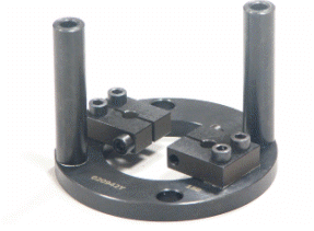
- Assemble a dial gauge on the specific tool.
Specific tooling
020942Y Piston protrusion check tool
- With a contrasting surface, reset the dial gauge with a preloading of a few millimetres.
- Finally fix the dial gauge.
- Check the perfect sliding of the feeler pin.
- Fit the tool on the cylinder without changing the dial gauge position.
- Lock the tool with the original head fixing nuts.
- Rotate the crankshaft up to TDC (the reversal point of the dial gauge rotation).
- Measure the deviation from the reset value.
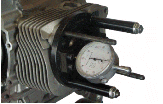
- By means of the table, see the Specifications chapter identify the cylinder base gasket thickness to be used for refitting. Correctly identify the cylinder base gasket thickness to keep the correct compression ratio.
- Remove the specific tool and the cylinder.
Refitting the piston rings
- Pistons (like cylinders) are supplied in 4 categories: A, B, C and D, and must be fitted so that the reference arrow faces the exhaust duct. The letter is found at the centre of the piston.
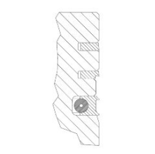
- Fit the sealing rings with the word TOP or the identification letter facing upwards. In any case, the step must be facing opposite the piston crown.
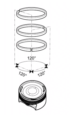
- Sealing rings are manufactured with a cylinder contact conical cross-section and piston gaps must be offset by 120º in order to obtain a better bedding.
- Lubricate rings with engine oil when fitting them.
CAUTION
AT EVERY NEW MOUNTING USE RETAINER RING PINS.
Refitting the cylinder
- Fit the cylinder base gasket of the chosen thickness.
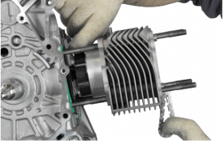
- Using the fork support and the piston ring retaining band, refit the cylinder as shown in the figure.
N.B.
BEFORE FITTING THE CYLINDER, CAREFULLY BLOW AIR INTO THE LUBRICATION DUCT AND LUBRICATE THE CYLINDER LINER.
Specific tooling
020426Y Piston fitting fork
020427Y Piston fitting ring
Recommended products
eni i-Ride PG 5W-40 Synthetic based lubricant for high-performance four-stroke
engines.
JASO MA, MA2 - API SL - ACEA A3
Inspecting the cylinder head
N.B.
TO MEASURE WEAR LIMITS AND COUPLING CLEARANCES, SEE THE SPECIFICATIONS CHAPTER.
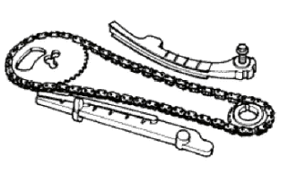
Inspecting the timing system components
- Check that the guide slider and the tensioner pad are not excessively worn.
- Ensure that the camshaft control pulley chain assembly and the sprocket wheel are not worn.
- If you detect wear, replace the parts or, if the chain, sprocket wheel and pulley are worn, replace the whole unit.
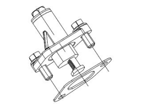
- Remove the centre screw with the washer and the tensioner spring. Check that the one-way mechanism is not worn.
- Check the condition of the tensioner spring.
- If signs of wear are found, replace the whole assembly.
Inspecting the valve sealings
N.B.
TO MEASURE WEAR LIMITS AND COUPLING CLEARANCES, SEE THE SPECIFICATIONS CHAPTER.
Inspecting the valves
N.B.
TO MEASURE WEAR LIMITS AND COUPLING CLEARANCES, SEE THE SPECIFICATIONS CHAPTER.
VALVE CLEARANCE CHECK
- Remove the cover.
- Position the engine to the TDC in compression
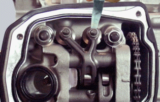
- Using a feeler gauge check the valve clearance.
CAUTION
- USE THE FEELER GAUGE LATERALLY, IN LINE WITH THE VALVES, IN ORDER TO PREVENT ACCIDENTAL BENDING OF THE BLADE THAT MAY AFFECT THE MEASUREMENTS.
Characteristic
Valve clearance (when cold)
intake: 0.08 mm exhaust: 0.08 mm
Inspecting the springs and half-cones
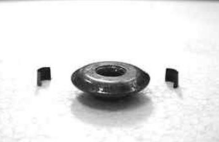
- Check that the upper and lower supporting spring washers, the cotters and the oil seal show exhibit no signs of abnormal wear. Replace a component when worn.
N.B.
TO MEASURE WEAR LIMITS AND COUPLING CLEARANCES, SEE THE SPECIFICATIONS CHAPTER.
Refitting the valves
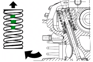
CAUTION
MOUNT THE VALVE SPRINGS WITH THE GREEN COLOURED COIL FACING UPWARD.
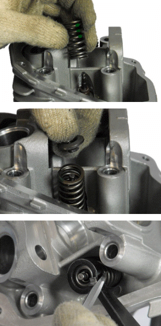
- Lubricate the valve guides with engine oil.
- Place the valve spring supports on the head.
- Using the special punch, fit the three valve seal rings alternately.
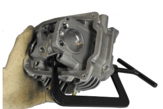
- Fit the valves, the springs and the caps. Using the appropriate tool with adapter, compress the springs and insert the cotters in their seats.
Specific tooling
020382Y Valve fitting/ removal tool
020431Y Valve oil seal extractor
Inspecting the cam shaft
N.B.
TO MEASURE WEAR LIMITS AND COUPLING CLEARANCES, SEE THE SPECIFICATIONS CHAPTER.
Refitting the head and timing system components
- Position the crankshaft to the TDC in compression
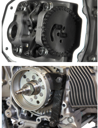
- Insert the head gasket and check the correct operation of the alignment dowels.
- Insert the chain guide slider.
- Insert the head.
- Lubricate the stud bolt threads with engine oil.
- Tighten the nuts to an initial pre-torque of 9-11 Nm.
- Tighten up the nuts by rotating 270.0+-5.0º with crossed sequence.
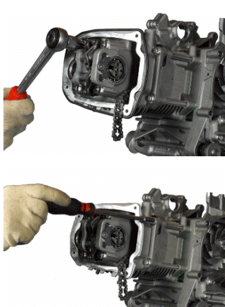
- Fit the two screws on the outside of the timing chain side and tighten them to the specified torque.
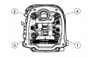
CAUTION
DO NOT PERFORM 270º IN ONE ROTATION. PERFORM WITH THREE GRADUAL ROTATIONS, OBSERVING THE SEQUENCE INDICATED ON THE STUD BOLTS.
N.B.
BEFORE INSTALLING THE HEAD, MAKE SURE THAT THE LUBRICATION CHANNEL IS CLEAN USING A COMPRESSED AIR JET.
CAUTION
ALWAYS USE A NEW HEAD GASKET UPON REFITTING.
Locking torques (N*m)
Cylinder head nut (TIGHTENING) 9 to 11 (Tighten to the prescribed torque and
then proceed with 270.0º+-5.0º rotation) Screws fixing cylinder to crankcase
10.8 to 12.7
Refitting the rocker-arms cover
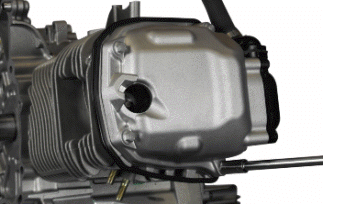
- Remove the cylinder head cover and tighten the four clamping screws to the prescribed torque.
- Pay attention to the integrity of rubber gaskets, replace them if necessary.
- Make sure the gasket is positioned properly.
Locking torques (N*m)
Head cover screws 10.8 to 12.7
Refitting the intake manifold
- Follow the disassembly process in reverse order to refit.
Locking torques (N*m)
Intake manifold fixing screws 10.8 to 12.8
See also:
 Vespa Primavera 50 - Service manual > Flywheel cover
Cooling hood Unscrew the five indicated screws and remove the cooling cap.
 Vespa Primavera 50 - Service manual > Crankcase - crankshaft
Splitting the crankcase halves Undo the eight crankcase coupling screws. Separate the crankcase halves while keeping the crankshaft in one of these two halves. Only after the halves have been separated, can the crankshaft be checked.
 BMW R 1250 RT
 Kymco Agility 50
 Piaggio Liberty 50
 Yamaha aerox NS50
 Aprilia SR50R
 Kymco Agility 50
 Vespa Primavera 50
 Peugeot Speedfight