 Aprilia SR50R - Service manual > Electrical System
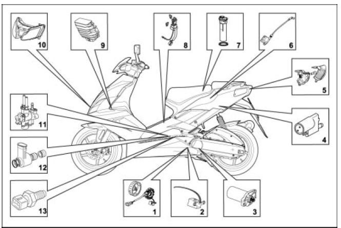
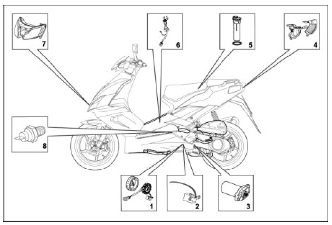
Checking the Electrical Components
CHECKING THE COMPONENTS IE361
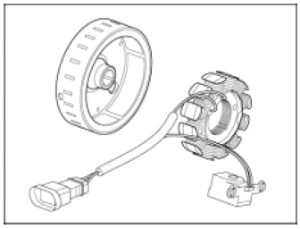
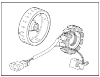
1. Generator:
three-phase generator
winding resistance: 1 ohm
output voltage 50AC (to be measured with the generator disconnected from wiring
system and the engine at 3000 rpm)

2. Rpm sensor:
inductive sensor
winding resistance: 110 ohms

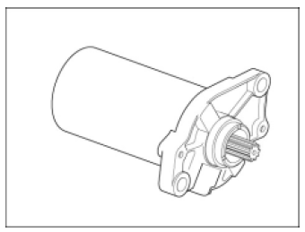
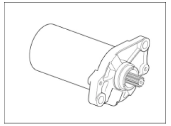
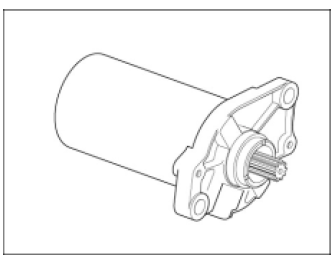
3. Starter motor
current absorbed in operation: 20 A
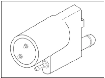
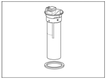
4. Fuel pump:
absorption: 0.35 A
5. Tail light:
parking/stop light : 12 V 5 / 21 W
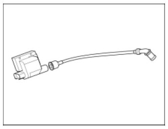
6. Ignition coil:
primary resistance: 0.7 ohms

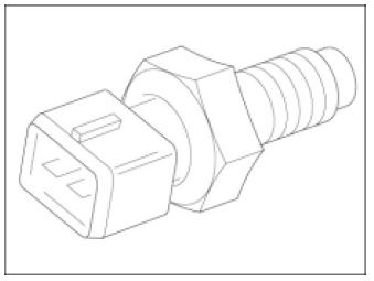
7 Fuel sensor:
resistance across terminals 1 and 3:
- 5 ohms with full fuel tank
- 38 ohms with half full fuel tank
- 100 ohms with empty fuel tank
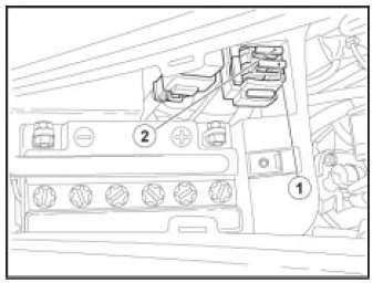
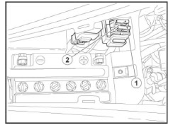
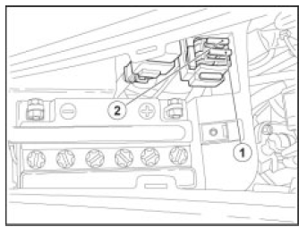
8. Fuses:
10A fuse (1) - From ignition switch to:
- Lights
- Low-High beam relay
- Horn
- Diagnostics circuit
15A fuse (2) - From battery to:
- Rectification/charge circuit
- Ignition switch
- Positive permanent on instrument panel
- Injection relay
- Engine kill switch
- Instrument panel key-operated power
- Stoplights
- Mixer oil reserve sensor
- Fuel sensor
- Coolant temperature sensor
9. Charging voltage:
voltage 13.5 V +- 0.3 V to be measured at battery poles (with engine at 3000 rpm)
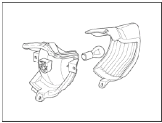
10. Headlight:
low beam 12 V 35 W
high beam 12 V 35 W
11. Throttle body
FUEL INJECTOR
winding resistance: 1.7 ohms
THROTTLE POSITION SENSOR (TPS):
- resistance across terminals 1 and 4: 1.1 kOhms
Throttle grip CLOSED
- resistance across terminals 1 and 2: 1.1 kOhms
- resistance across terminals 1 and 3: 1.9 kOhms
Throttle grip OPEN
- resistance across terminals 1 and 2: 1.9 kOhms
- resistance across terminals 1 and 3: 1.1 kOhms tolerance on measured values: +- 10%
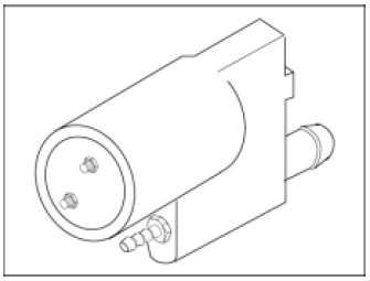
12. Air injector:
winding resistance: 1.3 ohms
13. Coolant temperature sensor
NTC sensor
resistance: 2.7 kOhms at 20 ºC
CHECKING THE COMPONENTS IE50
1. Generator:
three-phase generator
winding resistance: 1 ohm
output voltage 50AC (to be measured with generator disconnected from wiring
system and engine at 3000 rpm)
2. Rpm sensor:
inductive sensor
winding resistance: 110 ohms

3. Starter motor
current absorbed in operation: 20 A
4. Fuel pump:
absorption: 0.35 A
5. Tail lights:
parking/stop light 12 V 5 / 21 W
6. Ignition coil:
primary resistance: 0.7 ohms
7. Fuel sensor:
resistance across terminals 1 and 3:
- 5 ohms with full fuel tank
- 38 ohms with half full fuel tank
- 100 ohms with empty fuel tank
8. Fuses:
10A fuse (1 - 2) - From ignition switch to:
- Horn
- Rectification/charge circuit
- Stoplights
- Injection relay
- Engine kill switch
- Instrument panel key-operated power
- Turn indicators
- Mixer oil reserve sensor
- Fuel sensor
- Coolant temperature sensor
9. Charging voltage:
voltage 13.5 V +- 0.3 V to be measured at battery poles (with engine at 3000 rpm)
10. Headlight:
low beam 12 V 35 W
low/high beam 12 V 35 W
11. Throttle body
FUEL INJECTOR
winding resistance: 1.7 ohms
THROTTLE POSITION SENSOR (TPS):
- resistance across terminals 1 and 4: 1.1 kOhms
Throttle grip CLOSED
- resistance across terminals 1 and 2: 1.1 kOhms
- resistance across terminals 1 and 3: 1.9 kOhms
Throttle grip OPEN
- resistance across terminals 1 and 2: 1.9 kOhms
- resistance across terminals 1 and 3: 1.1 kOhms tolerance on measured values: +- 10%
12. Air injector:
winding resistance: 1.3 ohms
13. Coolant temperature sensor
NTC sensor
resistance: 2.7 kOhms at 20 ºC
CHECKING THE COMPONENTS C364
1. Generator:
two-phase generator
winding resistance: 0.5-1 ohms
output voltage 30-35 VAC (to be measured with generator disconnected from wiring
system and engine cranking)
2. Rpm sensor:
inductive sensor
winding resistance: 110 ohms
3. Starter motor
absorption in operation: 20 A.
4. Tail lights:
parking/stop light 12 V 5 / 21 W
5. Fuel sensor:
resistance (measure across pin 1 and 2)
- 5 ohms with full fuel tank
- 38 ohms with half full fuel tank
- 100 ohms with empty fuel tank
6. Fuses:
7.5A fuse (1) - From ignition switch to:
- Instrument panel key-operated power
- Stoplights
- Mixer oil reserve sensor
- Fuel sensor
- Coolant temperature sensor
- Turn indicator circuit
- Horn
- Diagnostics circuit
15A fuse (2) - From battery to:
- Rectification/charge circuit
- Ignition switch
- Positive permanent on instrument panel
7. Headlight:
low beam 12 V 35 W
high beam 12 V 35 W
8. Engine temperature sensor:
NTC sensor
resistance: 560 ohms (at 25ºC)
resistance: 40 ohms (at 100ºC)
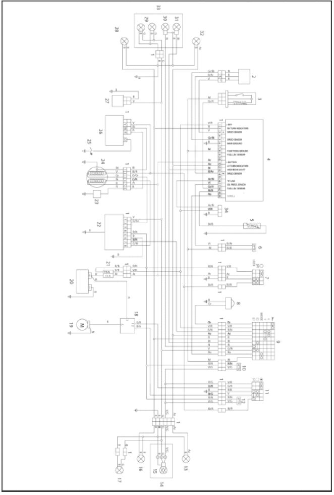
Wiring System Diagrams
WIRING DIAGRAM IE 361
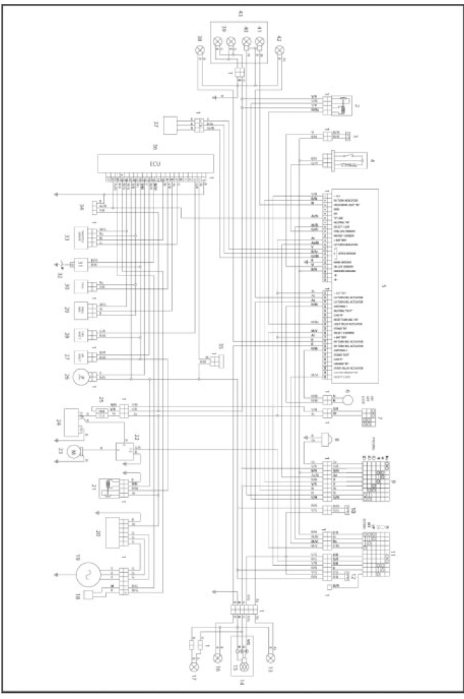
Key:
- Multiple connectors
- Low-High beam relay
- Oil level switch
- Fuel level sensor
- Instrument panel (matrix)
- Immobilizer antenna
- Key-operated switch
- Warning horn
- Left dimmer switch
- Rear stop switch (on left dimmer switch)
- Right dimmer switch
- Front stop switch (on right dimmer switch)
- Rear left turn indicator
- Tail light
- Parking light/brake light
- Rear right turn indicator
- License plate light (
 -
-
 only)
only) - Pick-up sensor
- Generator
- Voltage regulator
- Injection relay
- Starter relay (noise proof)
- Starter motor
- Battery
- Fuses
- Fuel pump
- Air injector
- Fuel injector
- Pressure sensor (or integrated in the control unit)
- Head temperature sensor
- H.T. coil
- Spark plug
- Throttle sensor
- Serial connector (diagnosis)
- Oil pump
- ECU
- Speed sensor
- Front right turn indicator
- Front parking lights (
 -
-
 only)
only) - Low beam
- High beam
- Front left turn indicator
- Headlight
- Diode
- -
- -
- -
- -
- -
WIRING DIAGRAM IE 50
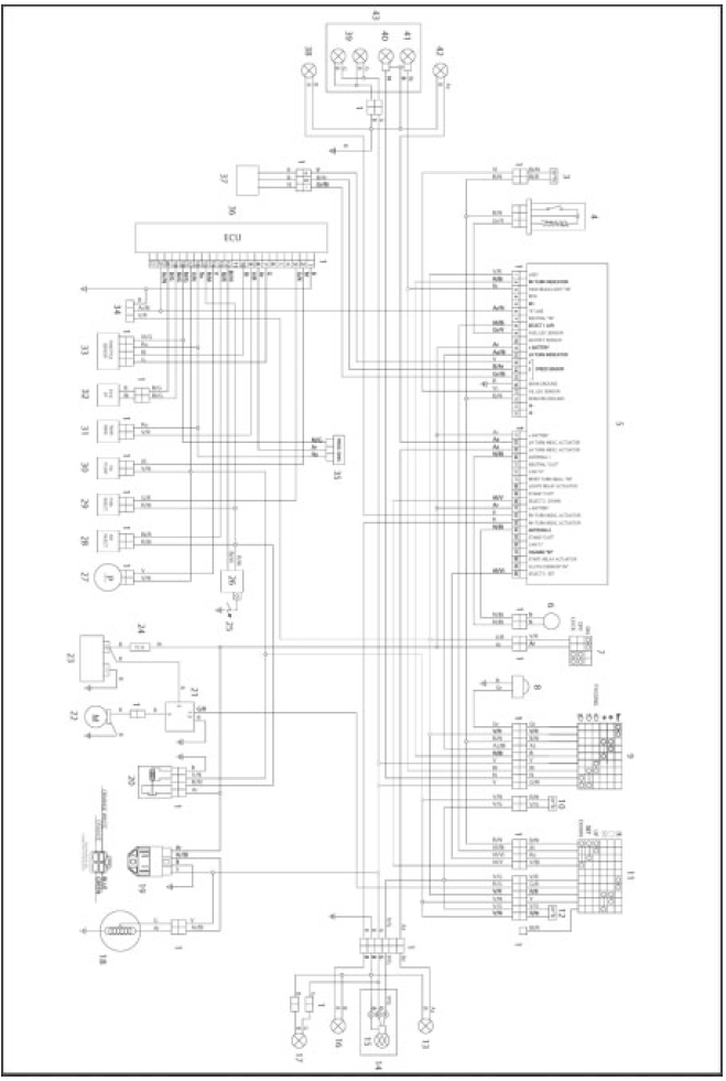
Key:
- Multiple connectors
- -
- Oil level switch
- Fuel level sensor
- Instrument panel (matrix)
- Immobilizer antenna
- Key-operated switch
- Warning horn
- Left dimmer switch
- Rear stop switch (on left dimmer switch)
- Right dimmer switch
- Front stop switch (on right dimmer switch)
- Rear left turn indicator
- Tail light
- Parking light/brake light
- Rear right turn indicator
- License plate light (
 -
-
 only)
only) - Generator
- Voltage regulator
- Injection relay
- Starter relay
- Starter motor
- Battery
- Fuse
- Spark plug
- H.T. coil
- Fuel pump
- Air injector
- Fuel injector
- Oil pump
- Temperature sensor
- Pick-up sensor
- Throttle sensor
- Serial connector (diagnosis)
- Pressure sensor (or integrated in the control unit)
- ECU
- Speed sensor
- Front right turn indicator
- Front parking lights (
 -
-
 only)
only) - Low beam
- High beam
- Front left turn indicator
- Headlight
- Diode
- -
- -
- -
- -
- -
CABLE COLORS
Ar Orange
Az Light blue
B Blue
Bi White
G Yellow
Gr Gray
M Brown
N Black
R Red
V Green
Vi Violet
Ro Pink
WIRING DIAGRAM C 364
Key:
- Multiple connectors
- Speed sensor
- Fuel level sensor
- Instrument panel (easy)
- Head temperature sensor
- Oil level switch
- Key ignition switch
- Warning horn
- Left dimmer switch
- Rear stop switch (on left dimmer switch)
- Right dimmer switch
- Front stop switch (on right dimmer switch)
- Rear left turn indicator
- Tail light
- Parking light/brake light
- Rear right turn indicator
- License plate light (
 -
-
 only)
only) - Starter relay
- Starter motor
- Battery
- Fuses
- Regulator
- Pick-up sensor
- Generator
- SPARK PLUG
- Transducer
- Automatic choke
- Front right turn indicator
- Front parking lights ( -
only)
- Low beam
- High beam
- Front left turn indicator
- Headlight
- Serial connector (diagnosis)
- -
- -
- -
- -
See also:
 Aprilia SR50R - Service manual > Front Fork
FRONT FORK DIAGRAM Key: Rubber cap Snap ring Fork clamp bolts Snap ring Sealing cap O-ring Rubber seal Spring Damping cylinder Counter spring Buffer Left slider Right slider Dust seal Snap ring Seal Left stanchion tube Right stanchion tube Securing screws Sealing washer Capscrew
 BMW R 1250 RT
 Kymco Agility 50
 Piaggio Liberty 50
 Yamaha aerox NS50
 Aprilia SR50R
 Kymco Agility 50
 Vespa Primavera 50
 Peugeot Speedfight