 Vespa Primavera 50 - Service manual > Fuel supply system
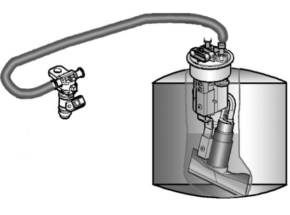
The fuel system circuit includes the electric pump, the filter, the pressure regulator, the electro-injector and the fuel delivery pipes.
The electrical pump is located in the tank from which the fuel is pumped and sent to the injector through the filter.
The pressure is controlled by the pressure regulator situated in the pump assembly in the tank.
Removing the injector
- Remove the helmet compartment.
- Disconnect the connector from the injector.
- Disconnect the quick release of the petrol delivery pipes.
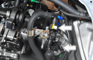
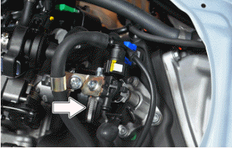
- Undo the fixing screws and slide the injector from the manifold being careful not to damage the sealing OR gasket.
CAUTION
DO NOT DISASSEMBLE THE INJECTOR COMPONENTS.
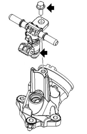
Refitting the injector
For refitting, perform the removal operations in reverse order and lubricate the sealing OR gasket with grease for internal application before fitting the injector on the manifold.
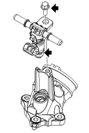
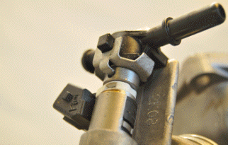
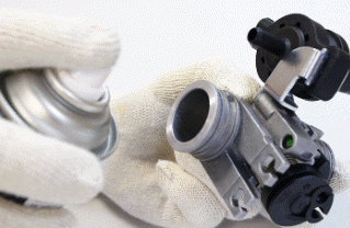
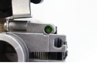
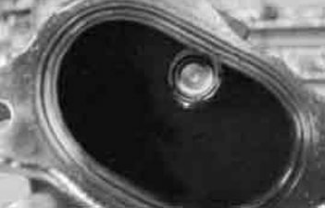
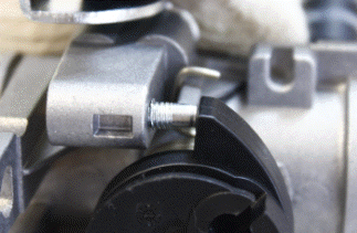
- The injector on this vehicle is a twin head injector with angle different to 90º, an incorrect positioning of the injector in the throttle body can cause serious malfunction; it must be observed that the pin of the spring is placed inside the recess in the injector body as shown in figure.
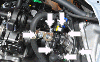
Removing the butterfly valve
- Remove the throttle grip cables.
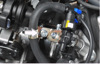
- Remove the indicated screw.
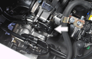
- Remove the clamp indicated in the photograph.
- Remove the connector of the idling adjustment device.
- Remove the clamps indicated in the figure.
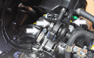
- Disconnect the throttle position sensor connector.
- Clean the throttle body according to the scheduled maintenance.
WARNING
AFTER MAINTENANCE OPERATIONS, IT IS RECOMMENDED TO DELETE THE SELF-ADJUSTABLE PARAMETERS.
Recommended products
Cleaner for throttle bodies Spray cleaner for throttle bodies
Detergent for throttle bodies
Refitting the butterfly valve
- To refit, follow the operations, but in reverse order, every time the throttle position sensor is disconnected it is necessary to calibrate the self-adjusting parameters.
Do not tamper with the stop screws under the throttle body.
CAUTION
DO NOT TAMPER WITH THE STOP SCREWS UNDER THE THROTTLE BODY, AS THE IDLE SPEED IS ADJUSTED IN THE FACTORY.
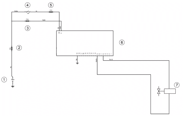
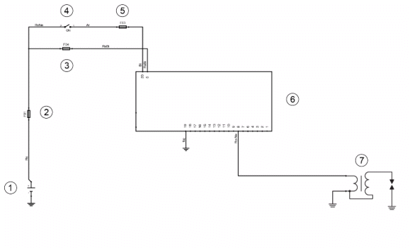
Pump supply circuit
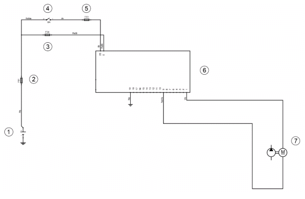
- Battery
- Fuse No. 1
- Fuse no. 4
- Ignition switch
- Fuse no. 3
- CDI control unit
- Fuel pump
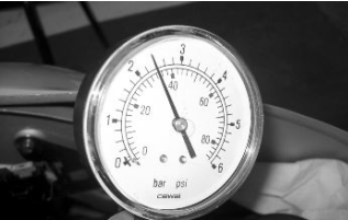
Circuit leak test
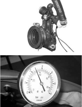
Install the specific tool for checking the fuel pressure, with the pipe fitted with the gauge.
Check during regular operation by placing the appropriate tool between the pump and the injector.
With the battery voltage > 12 V check that the fuel pressure is 2.5 BAR and that the input current is 1.4 to 1.8 A.
With the battery voltage > 12 V, check the pump flow rate by disconnecting from the injector the pipe equipped with the pressure gauge of the appropriate tool. Make a graded burette available with a flow rate of approximately 1 L. Rotate the pump using the active diagnosis of the palm top computer. Using a pair of long flat needle-nose pliers, choke the fuel pipe making the pressure stabilise at approx. 2.5 bar. Check that within 15 seconds the pump has a flow rate of approx. 110 cm³.
Specific tooling
020480Y Fuel pressure check set
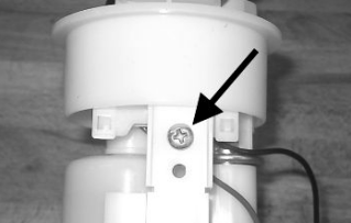
Fuel filter check
After removing from the tank, disconnect the electric pump terminals.
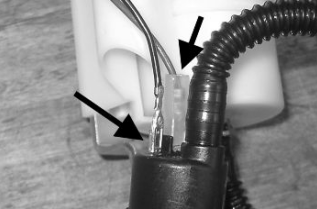
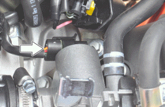
Remove the screw indicated in the photograph
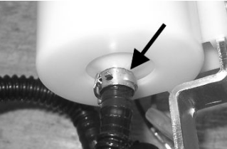
Remove the clamp fixing the piping to the filter shown in the photograph
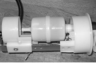
Separate the lower part of the pump support as shown in the photograph.
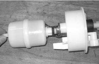
Remove the filter from the pump support
Inspecting the injector circuit
- Battery
- Fuse No. 1
- Fuse no. 4
- Ignition switch
- Fuse no. 3
- CDI control unit
- Injector
Checking the resistance at the injector ends: 14.5 +- 5% Ohm
Inspecting the injector hydraulics
To carry out the injector check, remove the intake manifold by removing the three screws, with antitampering device, fixing the head and loosening the clamp connecting the throttle body to the manifold.
Disconnect the electrical connector.
Release the injector fuel delivery pipe from the bracket on the throttle body and from the clamp fixing it to the wiring.
Install the appropriate tool for checking fuel pressure and position the manifold over a container graduated by at least 100 cm³. Connect the injector with the cable making up part of the supply for the injection tester. Connect the clamps of the cable to an auxiliary battery. Activate the fuel pump with the active diagnosis. Check that, within fifteen seconds, approximately 40 cm³ of fuel is dispensed with an adjustment pressure of approximately 2.5 BAR.
Specific tooling
020480Y Fuel pressure check set
Proceed with the injector seal test.
Dry the injector outlet with a blast of compressed air. Activate the fuel pump. Wait for one minute, making sure there are no leaks coming from the injector. Slight oozing is normal.
Value limit = 1 drop per minute
HT coil
- Battery
- Fuse No. 1
- Fuse no. 4
- Ignition switch
- Fuse no. 3
- CDI control unit
- Coil
The combined ignition/injection system is a high-efficiency induction system.
The control unit manages two significant parameters:
- Ignition advance
This is optimised at the moment in accordance with the engine revs, engine load, temperature and environmental pressure.
With the engine at idle, the ignition advance is optimised to stabilise the speed at 1450 +- 50 rpm.
- Magnetisation time
The coil magnetisation time is controlled by the control unit. The power of the ignition is increased during the engine start-up phase.
The injection system recognises the 4-stroke cycle so ignition is only commanded in the compression phase.
Specific tooling
020331Y Digital multimeter
Zeroing the throttle
Resetting the throttle valve position signal (TPS reset)
The throttle body is supplied with throttle valve position sensor and is pre-calibrated.
Pre-calibration entails regulating the minimum opening of the throttle valve to obtain a certain flow of air under pre-set reference conditions.
Pre-calibration ensures optimal air flow to control idling.
This regulation must not be tampered with in any way whatsoever.
The injection system will complete the management of the idling through the related device and the variation of the ignition advance.
The throttle body after the pre-calibration has an opened valve with an angle that can vary depending on the tolerances of the machining of the pipe and the valve itself.
The valve position sensor can also assume various fitting positions. For these reasons the mV of the sensor with the valve at idle can vary from one throttle body to another.
To obtain the optimum fuel mixture, especially at small openings of the throttle valve, it is essential to match the throttle body with the control unit following the procedure known as TPS resetting.
With this operation we inform the control unit, as the starting point, of the mV value corresponding to the pre-calibrated position.
To reset, proceed as follows.
Connect the diagnostic tester.
Shift to "ON".
Select the functions of the diagnostic tester on "TPS RESET".
Specific tooling
020922Y Diagnosis Tool
Make sure that the throttle valve control is in contact with the stop screw.
With the throttle completely closed, check that the cables have clearance in all steering positions and confirm the position at the diagnostics instrument.
Keep the throttle in a completely open position and confirm the position at the diagnostics instrument.
CAUTION
DO NOT TAMPER WITH THE STOP SCREWS UNDER THE THROTTLE BODY, AS THE IDLE SPEED IS ADJUSTED IN THE FACTORY.
See also:
 Vespa Primavera 50 - Service manual > Precautions
Troubleshooting tips 1 - An injection system failure is more likely to be due to the connections than to the components. Before troubleshooting the injection system, carry out the following checks: Electrical power supply Battery voltage Blown fuse Relays Connectors Chassis ground Fuel system Broken fuel pump Dirty fuel filter Ignition system Faulty spark plug Broken coil Broken shielded cap Intake circuit Dirty air filter Dirty by-pass circuit Idle speed adjustment device Other Incorrect distribution timing Wrong idle mixture Incorrect reset of the throttle valve position sensor
Vespa Primavera 50 - Service manual > Suspensions
N.B. THE UNITS OF MEASUREMENT CONTAINED IN THIS CHAPTER ARE EXPRESSED IN TERMS OF THE DECIMAL METRIC SYSTEM. TO REFER TO THE UNIT OF MEASUREMENT EXPRESSED IN TERMS OF THE ANGLO-SAXON SYSTEM, SEE THE "CHARACTERISTICS" CHAPTER.
 BMW R 1250 RT
 Kymco Agility 50
 Piaggio Liberty 50
 Yamaha aerox NS50
 Aprilia SR50R
 Kymco Agility 50
 Vespa Primavera 50
 Peugeot Speedfight