 Vespa Primavera 50 - Service manual > Precautions
Troubleshooting tips
1 - An injection system failure is more likely to be due to the connections than to the components.
Before troubleshooting the injection system, carry out the following checks:
- Electrical power supply
- Battery voltage
- Blown fuse
- Relays
- Connectors
- Chassis ground
- Fuel system
- Broken fuel pump
- Dirty fuel filter
- Ignition system
- Faulty spark plug
- Broken coil
- Broken shielded cap
- Intake circuit
- Dirty air filter
- Dirty by-pass circuit
- Idle speed adjustment device
- Other
- Incorrect distribution timing
- Wrong idle mixture
- Incorrect reset of the throttle valve position sensor
2 - Injection system failure may be caused by loose connectors. Make sure that all connections have been correctly made.
Check the connectors taking into consideration the following point:
- check that the terminals are not bent.
- check that the connectors have been properly connected.
- check whether the malfunction can be fixed by shaking the connector slightly.
3 - Check the entire system before replacing the injection control unit. If the fault is fixed even by replacing the control unit, install the original control unit again and check if the fault occurs again.
4 - For troubleshooting, use a multimeter with an internal resistance of more than 10 K W /V. Improper instruments may damage the injection control unit. The instruments to be preferred have a definition over 0.1V and 0.5 W and an accuracy over 2%.
1. Before repairing any part of the injection system, check if any faults have been stored. Do not disconnect the battery before checking for faults.
2. The fuel system is pressurised at 250 kPa (2.5 BAR). Before disconnecting the fast-release fitting of the fuel supply pipe, check that there are no naked flames. Do not smoke. Act with caution to avoid spraying fuel to your eyes.
3. When repairing electric components, the battery must always be disconnected unless it is strictly necessary for the battery to be connected.
4. When functional checks are performed, make sure that the battery voltage exceeds 12V.
5. Before attempting to start the vehicle, ensure that there are at least two litres of fuel in the tank.
Failure to respect this norm will damage the fuel pump.
6. If a long period is envisaged with the vehicle not in use, fill the tank to at least the halfway mark. This will ensure the pump will be covered by fuel.
7. When washing the vehicle, do not spray excessive water on electric components and wiring.
8. In the event of ignition problems, begin troubleshooting from the battery and the injection system connections.
9. Before disconnecting the connector of the injection control unit, perform the following steps in the order shown:
- Set the switch to "OFF"
- Disconnect the battery
Failure to respect this norm may damage the control unit.
10. Do not invert the poles when fitting the battery.
11. To avoid causing any damage, disconnect and reconnect the injection system connectors only if required. Before reconnecting, check that the connectors are dry.
12. When carrying out electric inspections, do not force the tester probes into the connectors. Do not take measurements not specifically foreseen by the manual.
13. At the end of every check performed with the diagnostic tester, remember to protect the system connector with its cap. Failure to observe this precaution may damage the injection control unit.
14. Before reconnecting the quick couplers of the power supply system, check that the terminals are perfectly clean.
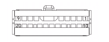
Terminals setup
INJECTION ECU
- Ve - fuel pump
- MaBi - injection warning light
- AzRs -lambda probe heater
- Gi - immobilizer LED
- RsBi - + battery
- RsGi - injector ground
- GrVe - Sensor ground
- RoNe - + H.V. coil
- NeVe - + loads
- ArNe - K Line
- VeBi - lights enabling
- Rs - pickup +
- VeBL - Lambda +
- ArBi - TPS sensor
- Ar - Engine stop switch
- AzVe - Engine temperature sensor
- BiNe - Idle adjustment valve
- RsNe - +5V sensors
- Ne - Ground
- Bi - + key
EMS circuit diagram
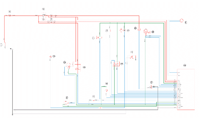
KEY
1. Battery
4. Main fuse
5. Ignition switch
6. Secondary fuses
21. Starter relay coil
34. Roll-over sensor
35. engine stop switch
36. Immobilizer LED
41. Injector
42. Idle valve
43. Engine speed sensor
44. Engine temperature sensor
45. Lambda probe
46. Fuel pump
47. HV coil
48. Injection warning light
49. Throttle body position
50. Diagnostics socket
51. Immobilizer aerial
52. Injection ECU
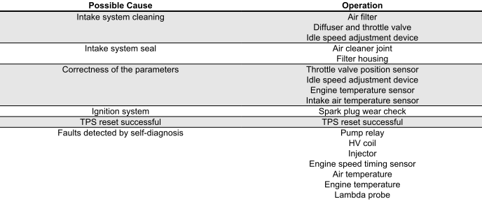
Troubleshooting procedure
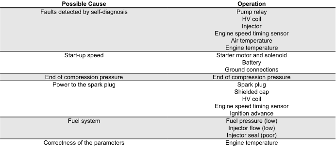
Engine does not start
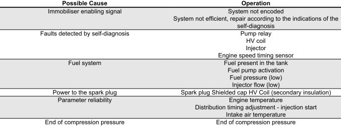
ENGINE DOES NOT START EVEN IF PULLED
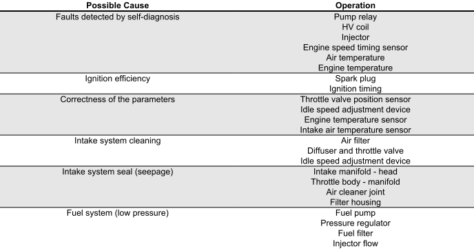
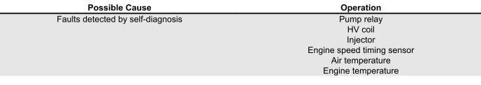
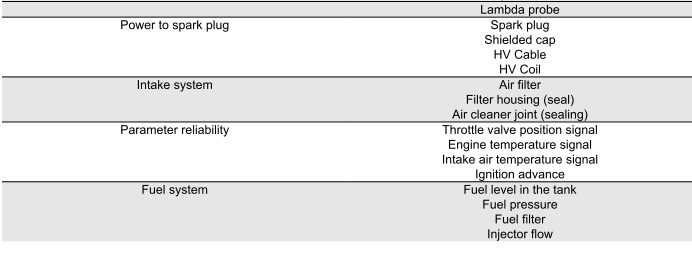
Starting difficulties
ENGINE STARTER PROBLEMS

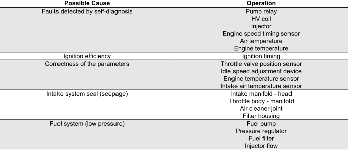
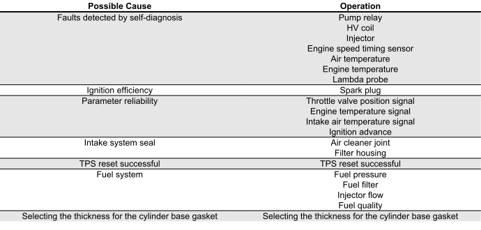
Engine stops at idle
ENGINE DOES NOT IDLE/ IDLING IS UNSTABLE/ IDLING TOO LOW
Engine does not rev down
ENGINE DOES NOT RETURN TO IDLING SPEED/IDLING SPEED TOO HIGH
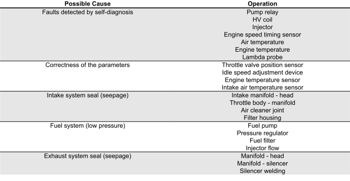
Exhaust backfires in deceleration
EXHAUST BACKFIRES WHEN DECELERATING
Engine revs irregularly
ENGINE IRREGULAR PERFORMANCE WITH VALVE SLIGHTLY OPEN
Poor performance at full throttle
POOR ENGINE PERFORMANCE AT FULL POWER/ IRREGULAR ENGINE PROGRESS ON ACCELERATION
Engine knocking
PRESENCE OF KNOCKING (COMBUSTION SHOCKS)
See also:
 Vespa Primavera 50 - Service manual > Injection
Injection system This vehicle is fitted with an integrated injection and ignition system. Injection is indirect in the manifold through an electro-injector.
Vespa Primavera 50 - Service manual > Fuel supply system
The fuel system circuit includes the electric pump, the filter, the pressure regulator, the electro-injector and the fuel delivery pipes. The electrical pump is located in the tank from which the fuel is pumped and sent to the injector through the filter.
 BMW R 1250 RT
 Kymco Agility 50
 Piaggio Liberty 50
 Yamaha aerox NS50
 Aprilia SR50R
 Kymco Agility 50
 Vespa Primavera 50
 Peugeot Speedfight