 Vespa Primavera 50 - Service manual > Diagnostic instrument
BATTERY
ELECTRICAL ERRORS
Low power supply P0562
Error cause
The battery voltage is below the minimum threshold.
Troubleshooting
Check the battery, the voltage regulator, the correct function of the alternator (flywheel) and the relative connectors.
High power supply P0563
Error cause
The battery voltage is below the minimum threshold.
Troubleshooting
Check the battery, the voltage regulator, the correct function of the alternator (flywheel) and the relative connectors.
IMMOBILIZER AERIAL
Function
Detects the transponder code in the key and sends it to the engine control unit.
ERRORS
Immobilizer P0513 - unknown transponder.
Error cause
The key has the working transponder, but it is not within the recognised ones.
Troubleshooting
Store the new key.
Immobilizer P1514 - not working antenna or key without transponder.
Error cause
Antenna electrical fault or the key has no transponder or the transponder is damaged.
Troubleshooting
Replace the key and store it if necessary. If the error persists, check the electrical characteristics and the continuity of the antenna circuit:
- Disconnect the antenna connector and check the correct resistance value at the ends.
- Check wiring continuity between the antenna and the engine control unit and restore if necessary.
Electric characteristic
Resistance at 20ºC
7.66 +- 5% Ω
H.V. COIL
Function
Allows generation of the electrical discharge on the spark plug, with an increase of voltage.
Pin-out:
- Control unit power
- Ground lead
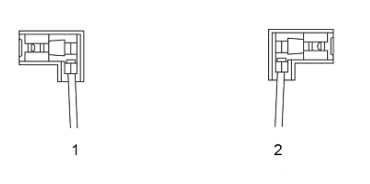
ELECTRICAL ERRORS
H.V. coil P0351 - open circuit.
Error cause
Open circuit: circuit interruption.
Troubleshooting
Open circuit:
- Carry out the check procedure of the coil and control unit connectors.
- Check the ground and battery-powered insulation of coil PIN 1.
- Verify continuity of the cabling between the coil and control unit: Coil PIN 1 - control unit PIN 8. If there is no continuity, restore the cable harness.
- Check the ground connection of coil PIN 2. If necessary, restore the cable harness.
- If the above tests provided a positive result, the coil should be replaced.
INJECTOR
Function
Provide the correct amount of fuel at the correct time.
Operation / Operating principle
Injector coil is excited for the petrol passage to open.
Pin-out:
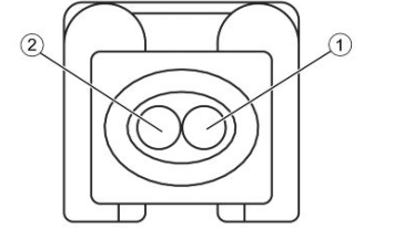
- Positive from control unit
- Negative from control unit (injector activation)
ELECTRICAL ERRORS
Low injector voltage P0261 - open circuit or short circuit to negative.
Error cause
Open circuit or short circuit to negative: interruption of the circuit or null voltage at PIN 2 of the injector connector.
Troubleshooting
Open circuit:
- Perform the check of the injector and control unit connectors.
- Check the continuity of the cable harness between the control unit connector and injector connector: Control unit PIN 6 - injector PIN 2 and control unit PIN 9 - injector PIN 1. If there is no continuity, restore the cable harness.
Short circuit to negative:
- Disconnect the control unit connector and the injector connector.
- Check the injector connector PIN 2 ground insulation (corresponding to
control unit connector PIN 6).
If there is no insulation, restore the cable harness.
- With the injector connector disconnected and the control unit connector connected, turn ignition switch to ON and activate the component using the diagnostic tool.
- Check if there is intermittent voltage (4 ms every second for 5 seconds) at the ends of the injector connector.
- If there is no voltage, check the continuity of the cable harness between control unit PIN 9 and injector PIN 1 and restore it if necessary.
- If the above tests provided a positive result, the injector should be replaced.
High injector voltage P0262 - shorted to positive.
Error cause
Short circuit to positive: excessive voltage to PIN 6 of the control unit connector.
Troubleshooting
Short circuit to positive:
- Disconnect the control unit connector and the injector connector.
- Verify that there is no short to battery positive on injector connector PIN 2 (corresponding to control unit connector PIN 6); if there is a short circuit, restore the cable harness.
- With the injector connector disconnected and the control unit connector connected, turn ignition switch to ON and activate the component using the diagnostic tool.
- Check if there is intermittent voltage (4 ms every second for 5 seconds) at the ends of the injector connector.
- If there is no voltage, check the continuity of the cable harness between control unit PIN 9 and injector PIN 1 and restore it if necessary.
- If the above tests provided a positive result, the injector should be replaced.
FUEL PUMP
Function
Pump fuel from the tank to introduce it in the injection circuit.
Pin-out:
- Not connected
- Negative from control unit (injector activation)
- Not connected
- Not connected
- Positive from control unit
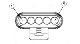
ELECTRICAL ERRORS
Low fuel pump voltage P0231 - open circuit or short circuit to negative.
Error cause
Open circuit or short circuit to negative: interruption of the circuit or null voltage at PIN 2 of the pump connector.
Troubleshooting
Open circuit:
- Perform the check of the fuel pump and control unit connectors.
- Check the continuity of the cable harness between the control unit connector and pump connector: Control unit PIN 1 - pump PIN 2 and control unit PIN 9 - pump PIN 5. If there is no continuity, restore the cable harness.
Short circuit to negative:
- Disconnect the control unit connector and the pump connector.
- Check the pump connector PIN 2 ground insulation (corresponding to
control unit connector PIN 1).
If there is no insulation, restore the cable harness.
High fuel pump voltage P0232 - shorted to positive.
Error cause
Short circuit to positive: excessive voltage at PIN 1 of the control unit connector.
Troubleshooting
Short circuit to positive:
- Disconnect the control unit connector and the pump connector.
- Verify that there is no short to battery positive on pump connector PIN 2 (corresponding to control unit connector PIN 1); if there is a short circuit, restore the cable harness.
ENGINE TEMPERATURE SENSOR
Function
Serves the purpose of communicating the engine temperature to the control unit in order to optimise performance.
Operation / Operating principle
NTC type sensor (resistance sensor, inversely variable with temperature).
Pin-out:
- Injection ECU
- Control unit ground
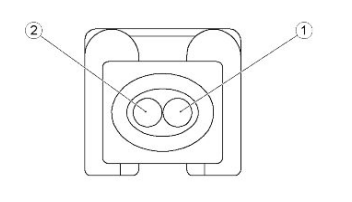
ELECTRICAL ERRORS
Low engine temperature sensor voltage P0117 - shorted to negative.
Error cause
Short circuit to negative:null voltage at PIN 16 of the control unit connector.
Troubleshooting
Short circuit to negative:
- Disconnect the sensor connector.
- Check the sensor connector PIN 1 ground insulation.
- If there is no ground insulation restore the cabling.
High engine temperature sensor P0118 - open circuit or shorted to positive.
Error cause
Open circuit or short circuit to positive: interruption of the circuit or excessive voltage at PIN 16 of the control unit connector.
Troubleshooting
Open circuit:
- Disconnect control unit and sensor connectors and carry out the check procedure.
- Check the continuity of the cable harness between the sensor connector and control unit connector: Sensor PIN 1- control unit PIN 16 and sensor PIN 2- control unit PIN 7. If necessary, restore the cable harness.
Short circuit to positive:
- With the sensor connector and the control unit disconnected, verify that the fault is a short with the battery positive of sensor connector PIN 1(or control unit PIN 16) and restore wiring.
THROTTLE BODY POSITION SENSOR (TPS)
Function
In charge of sending the size of throttle opening to the control unit.
Pin-out:
- Control unit ground
- Control unit power
- Throttle position signal
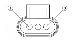
ELECTRICAL ERRORS
Low TPS sensor voltage input P0122 - open circuit or short circuit to negative.
Error cause
Open circuit or short circuit to negative: interruption of the circuit or null voltage at PIN 7, 14 or 18 of the control unit connector.
Troubleshooting
Open circuit:
- Disconnect control unit and sensor connectors and carry out the check procedure.
- Check the continuity of the cable harness between the sensor connector and control unit connector: Sensor PIN 1 - control unit PIN 7, sensor PIN 2 - control unit PIN 18 and sensor PIN 3 - control unit PIN 14. If necessary, restore the cable harness.
Short circuit to negative:
- Disconnect the sensor connector.
- Check the ground insulation of the three PIN of the sensor connector.
- If there is no ground insulation restore the cabling.
High sensor voltage input P0123 - shorted to positive.
Error cause
Short circuit to positive: excessive voltage to PIN 7, 14 or 18 of the control unit connector.
Troubleshooting
Short circuit to positive:
- With the sensor connector and the control unit connector disconnected, verify that the fault is shorted with the battery positive of one of the three PIN of the sensor connector and restore the cable harness.
LAMBDA PROBE
Function
In charge of telling the control unit whether the mixture is lean or rich.
Operation / Operating principle
Based on the difference of oxygen in the exhaust fumes and the environment, this generates voltage which is read and interpreted by the injection control unit. It does not require an external supply source but, in order to work properly, it should reach a high operating temperature: that is why there is a heating circuit inside.
Pin-out:
- Heater power
- Heater ground
- Sensor signal +
- Sensor signal -
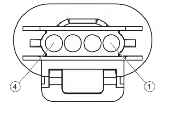
ELECTRICAL ERRORS
Low lambda probe voltage P0131 - shorted to negative.
Error cause
Short circuit to negative: null voltage at PIN 13 of the control unit connector.
Troubleshooting
Short circuit to negative:
- Disconnect the connector of the probe and the control unit connector and carry out the check procedure.
- Check the sensor connector PIN 3 from ground insulation. If there is no insulation, restore the cable harness.
High Lambda probe voltage P0132 - shorted to positive.
Error cause
Short circuit to positive: excessive voltage to PIN 13 of the control unit connector.
Troubleshooting
Short circuit to positive:
- Disconnect the control unit connector and the probe connector and perform the check procedure.
- Verify that there is no short to battery positive on sensor connector PIN 3 (corresponding to control unit connector PIN 13); if there is a short circuit, restore the cable harness.
Low lambda probe voltage P0031 - open circuit or short circuit to negative.
Error cause
Open circuit or short circuit to negative: interruption of the circuit or null voltage at PIN 3 of the control unit connector.
Troubleshooting
Open circuit:
- Disconnect the control unit connector and the heater connector and perform the check procedure.
- Check the continuity of the cable harness between the sensor connector and control unit connector: Control unit PIN 3 - sensor PIN 2 and control unit PIN 9 - sensor PIN 1. If necessary, restore the cable harness.
- If the cable harness is intact and the error persists, proceed with the following checks.
Short circuit to negative:
- Disconnect the control unit connector and the heater connector and perform the check procedure.
- Check the sensor connector PIN 2 ground insulation (corresponding to
control unit connector PIN 3).
If there is no insulation, restore the cable harness.
High heater lambda probe voltage P0032 - shorted to positive.
Error cause
Short circuit to positive: excessive voltage to PIN 3 of the control unit connector.
Troubleshooting
Short circuit to positive:
- Disconnect the control unit connector and the heater connector and perform the check procedure.
- Verify that there is no short to battery positive on sensor connector PIN 2 (corresponding to control unit connector PIN 3); if there is a short circuit, restore the cable harness.
IDLE VALVE
Function
Check the minimum engine speed depending on the temperature and different load conditions.
Pin-out:
- Negative from control unit (valve activation)
- Positive from control unit
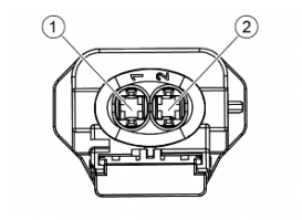
ELECTRICAL ERRORS
Low idling adjustment device voltage P0508 - open circuit or short circuit to negative.
Error cause
Open circuit or short circuit to negative: interruption of the circuit or null voltage at PIN 1 of the valve connector.
Troubleshooting
Open circuit:
- Perform the check of the valve and control unit connectors.
- Check the continuity of the cable harness between the control unit connector and valve connector: Control unit PIN 17 - valve PIN 1 and control unit PIN 9 - valve PIN 1. If there is no continuity, restore the cable harness.
Short circuit to negative:
- Disconnect the control unit connector and the valve connector.
- Check the valve connector PIN 1 ground insulation (corresponding to
control unit connector PIN 17).
If there is no insulation, restore the cable harness.
- With the valve connector disconnected and the control unit connector connected, turn ignition switch to ON and activate the component using the diagnosis tool.
- Check the voltage (for 10 seconds) at the ends of the valve connector.
- If there is no voltage, check the continuity of the cable harness between control unit PIN 9 and valve PIN 2 and restore it if necessary.
- If the above tests provided a positive result, the valve should be replaced.
High idling adjustment device voltage P0509 - shorted to positive.
Error cause
Short circuit to positive: excessive voltage to PIN 17 of the control unit connector.
Troubleshooting
Short circuit to positive:
- Disconnect the control unit connector and the valve connector.
- Verify that there is no short to battery positive on valve connector PIN 1 (corresponding to control unit connector PIN 17); if there is a short circuit, restore the cable harness.
- With the valve connector disconnected and the control unit connector connected, turn ignition switch to ON and activate the component using the diagnosis tool.
- Check the voltage (for 10 seconds) at the ends of the valve connector.
- If there is no voltage, check the continuity of the cable harness between control unit PIN 9 and valve PIN 2 and restore it if necessary.
- If the above tests provided a positive result, the valve should be replaced.
INJECTION WARNING LIGHT
Function
Indicates a fault of the injection system.
Instrument panel connector pin-out: 16. Injection warning light
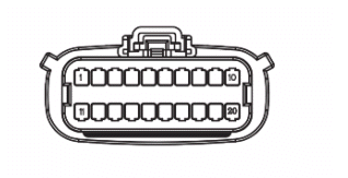
ELECTRICAL ERRORS
Low MIL warning light voltage P1651 - open circuit or short circuit to negative.
Error cause
Open circuit or short circuit to negative: interruption of the circuit or null voltage at PIN 2 of the control unit connector.
Troubleshooting
Open circuit:
- Disconnect the instrument panel connectors and of the control unit and perform the check procedure.
- Check the continuity of the cable harness between the control unit connector and instrument panel connector: Control unit PIN 2 - Instrument panel PIN 16. If necessary, restore the cable harness.
Short circuit to negative:
- Disconnect the instrument panel connectors and of the control unit and perform the check procedure.
- Check the instrument panel PIN 16 from ground insulation.
- If there is no ground insulation restore the cabling.
High MIL warning light voltage P1652 - shorted to positive.
Error cause
Short circuit to positive: excessive voltage at PIN 2 of the control unit connector.
Troubleshooting
Short circuit to positive:
- Disconnect the instrument panel connectors and of the control unit and perform the check procedure.
- Verify that the fault is shorted with the battery positive of instrument panel connector PIN 16 (or control unit connector PIN 2) and restore the cable harness.
If the above tests provided a positive result, proceed with the following check:
- Verify, with the key turned ON, the presence of voltage on the instrument panel connector PIN 16, otherwise check the related cable harnesses, the ignition switch contacts and the fuses 1 and 2.
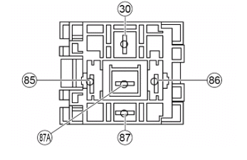
HEADLIGHT RELAY
Function
Controls the lights logic, the engine control unit modifies at idle speed the intensity of the headlight for maintaining battery.
Pin-out:
30. Battery positive
85. Live positive lead
86. Controlled by engine control unit
87. Headlight output
87A. Ground lead
ELECTRICAL ERRORS
Low headlamp voltage P1002 - shorted to negative.
Error cause
Short circuit to negative: null voltage at PIN 11 of the control unit connector.
Troubleshooting
Short circuit to negative:
- Remove the headlight relay from its base and ensure its correct functioning.
- Perform the check procedure of the control unit and relay base connector.
- Check the relay base connector PIN 86 from ground insulation.
- If there is no ground insulation restore the cabling.
High headlamp voltage P1001 - open circuit or short circuit to positive.
Error cause
Open circuit or short circuit to positive: interruption of the circuit or excessive voltage at PIN 11 of the control unit connector.
Troubleshooting
Open circuit:
- Disconnect the connector of the control unit.
- Remove the headlight relay from its base and ensure its correct functioning.
- Perform the check procedure of the control unit and relay base connector.
- Check continuity of the cable harness between the control unit and relay base Control unit PIN 11 - relay PIN 86. If necessary, restore the cable harness.
Short circuit to positive:
- With the headlight relay connector connected and the control unit disconnected, verify that the fault is a short circuit with the battery positive of sensor connector PIN 86 (or control unit PIN 11) and restore cable harness.
If the above tests provided a positive result, proceed with the following checks:
- Perform the check procedure of the control unit and relay base connector.
- Check the presence of fixed voltage on PIN 30 of the relay base, otherwise check the relative cable harnesses and the fuse no. 4.
- With the key set to ON, check the presence of voltage in the battery on the relay base connector PIN 85, otherwise check the related cable harnesses, the ignition switch contacts and fuses no.2 and 3.
- Check the ground connection of relay base PIN 87A.
- Check the continuity between relay base PIN 87 and lights switch connector.
See also:
 Vespa Primavera 50 - Service manual > Battery installation
VRLA battery (valve-regulated lead-acid battery) Maintenance Free (MF) WARNING BATTERY ELECTROLYTE IS TOXIC AND IT MAY CAUSE SERIOUS BURNS. IT CONTAINS SULPHURIC ACID. AVOID CONTACT WITH YOUR EYES, SKIN AND CLOTHING. IF IT ACCIDENTALLY COMES INTO CONTACT WITH YOUR EYES OR SKIN, WASH WITH ABUNDANT WATER FOR APPROX. 15 MIN. AND SEEK IMMEDIATE MEDICAL ATTENTION.
 Vespa Primavera 50 - Service manual > Engine from vehicle
N.B. THE UNITS OF MEASUREMENT CONTAINED IN THIS CHAPTER ARE EXPRESSED IN TERMS OF THE DECIMAL METRIC SYSTEM. TO REFER TO THE UNIT OF MEASUREMENT EXPRESSED IN TERMS OF THE ANGLO-SAXON SYSTEM, SEE THE "CHARACTERISTICS" CHAPTER.
 BMW R 1250 RT
 Kymco Agility 50
 Piaggio Liberty 50
 Yamaha aerox NS50
 Aprilia SR50R
 Kymco Agility 50
 Vespa Primavera 50
 Peugeot Speedfight