 Vespa Primavera 50 - Service manual > Battery installation
VRLA battery (valve-regulated lead-acid battery) Maintenance Free (MF)
WARNING
BATTERY ELECTROLYTE IS TOXIC AND IT MAY CAUSE SERIOUS BURNS. IT CONTAINS SULPHURIC ACID. AVOID CONTACT WITH YOUR EYES, SKIN AND CLOTHING. IF IT ACCIDENTALLY COMES INTO CONTACT WITH YOUR EYES OR SKIN, WASH WITH ABUNDANT WATER FOR APPROX. 15 MIN. AND SEEK IMMEDIATE MEDICAL ATTENTION.
IF ACCIDENTALLY SWALLOWED, IMMEDIATELY DRINK LARGE QUANTITIES OF WATER OR MILK FOLLOWED BY MAGNESIUM MILK, BEATEN EGG OR VEGETABLE OIL. SEEK IMMEDIATE MEDICAL ATTENTION.
BATTERIES PRODUCE EXPLOSIVE GASES; KEEP CLEAR OF NAKED FLAMES; VENTILATE THE AREA WHEN RECHARGING INDOORS.
ALWAYS WEAR EYE PROTECTION WHEN WORKING IN THE PROXIMITY OF BATTERIES.
KEEP OUT OF THE REACH OF CHILDREN
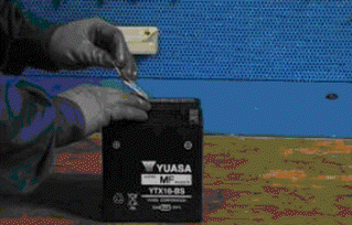
1) Battery preparation
Position the battery on a flat surface. Remove the adhesive sheet closing cells and proceed as quickly as possible to run the subsequent activation phases.
2) Electrolyte preparation.
Remove the container of the electrolyte from the pack. Remove and preserve cover strips from the container, in fact, the strip will later be used as a closing cover.
Note: Do not pierce the sealing of the container or the container itself because inside there is sulphuric acid.
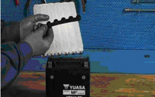
3) Procedure for filling the battery with acid.
Position the electrolyte container upside down with the six areas sealed in line with the six battery filler holes. Push the container down with enough force to break the seals. The electrolyte should start to flow inside the battery.
Note: Do not tilt the container to prevent the flow of electrolyte from pausing or stopping.
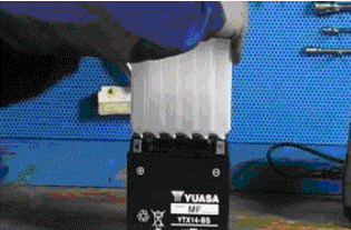
4) Control the flow of electrolyte
Make sure air bubbles are rising from all six filling holes. Leave the container in this position for 20 minutes or more.
Note: If there are no air bubbles coming out of the filling holes, lightly tap the bottom of the container two or three times. Do not remove the container from the battery.
5) Take out the container.
Make sure all the electrolyte in the battery is drained. Gently tap the bottom of the container if electrolyte remains in the container. Now, gently pull the container out from the battery, only do this when the container is completely empty, and proceed immediately to the next point.
6) Battery closing.
Insert the airtight cover strips into the filling holes. Press horizontally with both hands and make sure that the strip is levelled with the top part of the battery.
Note: To do this, do not use sharp objects that could damage the closing strip, use gloves to protect your hands and do not bring your face close to the battery.
The filling process is now complete.
Do not remove the strip of caps under any circumstances, do not add water or electrolyte.
Place the battery down for 1 to 2 hours prior to the charging from the battery.
7) Recharging the new battery
With the above-mentioned procedure, the battery will have gained around 70% - 75% of its total electrical capacity. Before installing the battery on the vehicle, it must be fully charged and then must be recharged.
If the battery is to be installed on the vehicle prior to this pre-charged one, the battery will not be able to exceed 75% charge without jeopardising its useful life on vehicle.
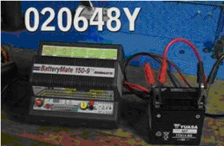
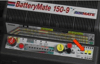
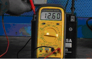
The dry charge battery MF like the completely loaded YTX, must have a no-load voltage between 12.8 - 13.15 V Bring the battery to full charge, using the 020648Y battery charger:
- select the type of battery with the red switch on the left of the panel battery charger panel
- select NEW on the yellow timer
- connect the clamps of the battery charger to the battery poles (black clamp to negative pole (-) and red clamp to positive pole (+) ).
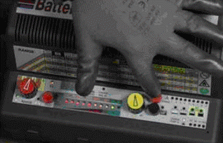
- Press the red button, as shown in figure.
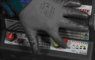
- Press the "MF" black button to activate the battery recharge Maintenance Free as shown in figure.
- Check the ignition of the green LED indicated with a red arrow in figure.
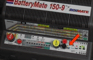
- The activation cycle of the new battery lasts for 30 minutes after the ignition of the recharge LED has taken place
- Disconnect the clamps from the battery and check the voltage, if voltages are detected of less than 12.8 V, proceed with a new recharge of the battery starting from point c of the recharge procedure of the new battery, otherwise go to point i
- The battery is now completely activated, disconnect the battery charger from the fuel supply grid, disconnect the clamps from the battery and proceed to fitting the battery on the vehicle.
Connectors
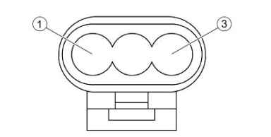
DIAGNOSTICS CONNECTOR
- Not connected
- Ground lead (Black)
- Electronic control unit (Orange-Black)
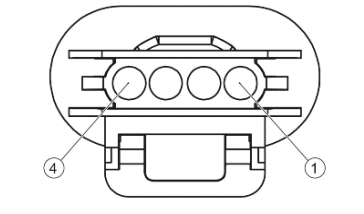
FLYWHEEL
a1. Gi - Voltage regulator
b1. GrVe - Pickup -
c1. Gi - Voltage regulator
a2. RoBi - Engine oil pressure sensor
b2. Gi - Voltage regulator
c2. Rs - Pickup +
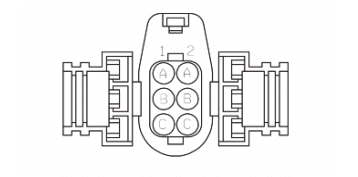
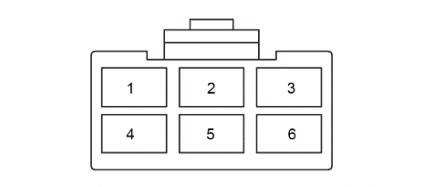
FUEL PUMP CONNECTOR
- Power from relay (Black - Green)
- Not connected
- Not connected
- Negative from control unit (Green)
- Not connected
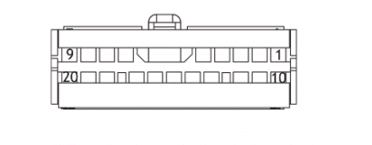
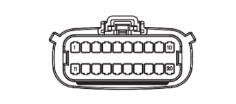
INJECTION ECU
- Ve - fuel pump
- MaBi - injection warning light
- AzRs -lambda probe heater
- Gi - immobilizer LED
- RsBi - + battery
- RsGi - injector ground
- GrVe - Sensor ground
- RoNe - + H.V. coil
- NeVe - + loads
- ArNe - K Line
- VeBi - lights enabling
- Rs - pickup +
- VeBL - Lambda +
- ArBi - TPS sensor
- Ar - Engine stop switch
- AzVe - Engine temperature sensor
- BiNe - Idle adjustment valve
- RsNe - +5V sensors
- Ne - Ground
- Bi - + key
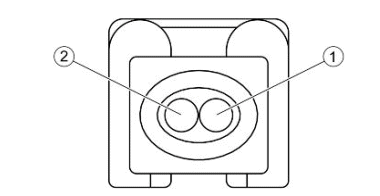
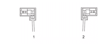
ENGINE TEMPERATURE SENSOR CONNECTOR
- Electronic control unit (Sky blue - Green)
- Ground lead (Grey-Green)
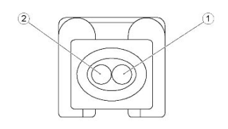
INJECTOR CONNECTOR
- Power from relay (Black - Green)
- Electronic control unit (Red - Yellow)
LAMBDA PROBE CONNECTOR
- Heater supply from ECU (Black-Green)
- Heater ECU negative (Light blue-Red)
- Lambda signal positive (Green-Blue)
- Lambda signal negative (Grey-Green)
VOLTAGE REGULATOR
- RsNe - positive
- Gr
- Ne - ground
- Gi - flywheel
- Gi - flywheel
- Gi - flywheel
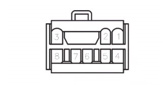
INSTRUMENT PANEL CONNECTOR
- Oil pressure sensor (Pink-White)
- MODE button (Green)
- Left turn indicator warning light (Pink)
- Right turn indicator warning light (White-Blue)
- High beam warning light (Purple)
- Ground lead (Black)
- Not connected
- Speed sensor negative (Black-Green)
- Not connected
- Not connected
- Not connected
- Fuel level indicator (White - Green)
- Not connected
- Speed sensor signal (Sky blue)
- Not connected
- Injection warning light (Brown-White)
- Ground lead (Black)
- Immobilizer LED (Yellow)
- Live power supply and instrument panel lighting (Yellow-Black)
- Battery-powered (Grey-Red)
H.V. COIL
- RoNe (black) - control unit
- Ne (green) - ground
ANTITHEFT DEVICE PRE-INSTALLATION CONNECTOR
- Ground lead (Black)
- Left indicator (White - Blue)
- Right indicator (Pink)
- Battery-powered (Grey-Red)
- Key powered (Yellow-Black)
- Not connected
- Not connected
- Not connected
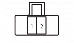
FUEL LEVEL TRANSMITTER CONNECTOR
- Fuel level indicator (White - Green)
- Ground lead (Black)
See also:
 Vespa Primavera 50 - Service manual > Starter motor
Battery Fuse No. 1 Starter relay Starter motor Ignition switch Fuse no. 2 Stop buttons Starter button CDI control unit
Vespa Primavera 50 - Service manual > Diagnostic instrument
BATTERY ELECTRICAL ERRORS Low power supply P0562 Error cause The battery voltage is below the minimum threshold.
 BMW R 1250 RT
 Kymco Agility 50
 Piaggio Liberty 50
 Yamaha aerox NS50
 Aprilia SR50R
 Kymco Agility 50
 Vespa Primavera 50
 Peugeot Speedfight