 Vespa Primavera 50 - Service manual > Electrical system installation
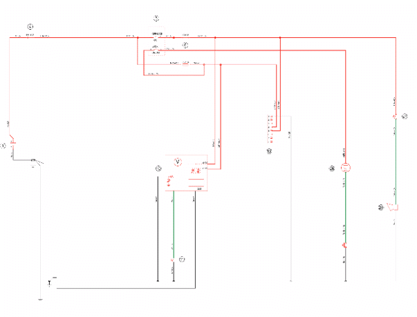
Front side
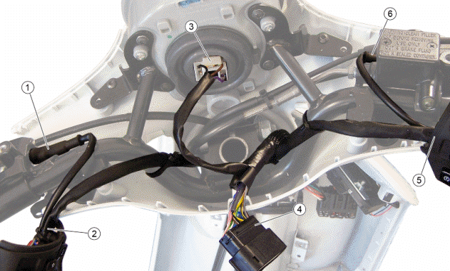
- Left stop button
- Left control lock
- Headlight connector
- Instrument panel connector
- Right control lock
- Right stop button
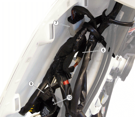
- Left electrical controls connector
- Ignition switch
- Voltage regulator
- Turn indicator control device
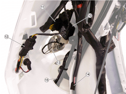
- Voltage regulator connector
- Front left turn indicator connector
- Horn connections
- Saddle opening switch connector
- To speed sensor on wheel
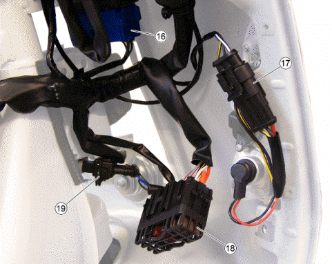
- Headlight relay base
- Front right turn indicator connect
- Secondary fuses
- Speed sensor connector
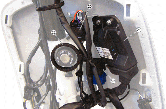
- Right electrical controls connector
- Injection ECU
- Immobilizer aerial
- Headlight relay
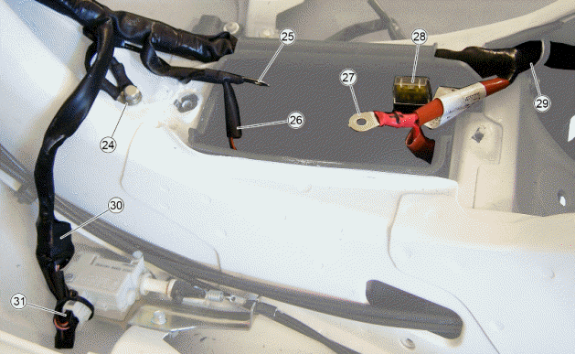
- Ground point on chassis
- Negative battery pole
- Diagnostics socket
- Positive battery pole
- Main fuse
- To rear cable harness
- Pre-installation for anti-theft device
- Saddle opening actuator connector
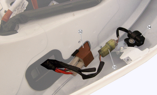
- Starter relay
- Roll-over sensor connector
- Roll-over sensor
Back side
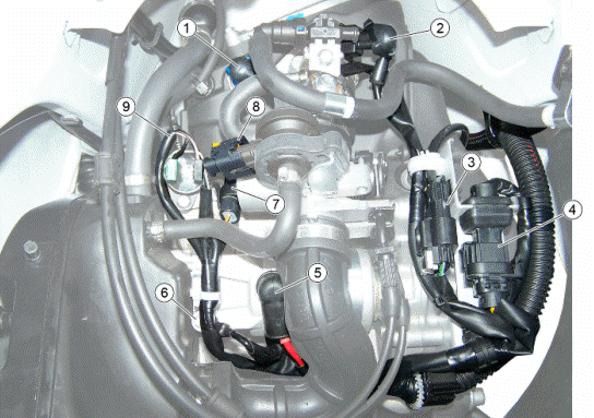
- Engine temperature sensor connector
- Injector connector
- Oxygen sensor connector
- Magneto flywheel connector
- Starter motor positive
- Starter motor negative
- Throttle body position sensor connector
- Idle valve connector
- H.V. coil connections
Conceptual diagrams
Ignition
KEY
1. Battery
4. Main fuse
5. Ignition switch
6. Secondary fuses
41. Injector
43. Engine speed sensor
44. Engine temperature sensor
45. Lambda probe
47. H.V. coil
49. Throttle body position
52. Injection ECU
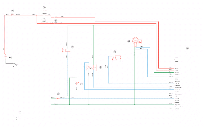
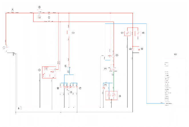
Battery recharge and starting
KEY
1. Battery
2. Starter relay contacts
3. Starter motor
4. Main fuse
5. Ignition switch
6. Secondary fuses
7. Voltage regulator
8. Magneto flywheel
18. Stop light
19. Stop buttons
20. Starter button
21. Starter relay coil
35. engine stop switch
52. Injection ECU
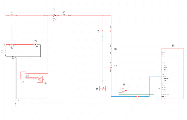
Level indicators and enable signals section
KEY
1. Battery
4. Main fuse
5. Ignition switch
6. Secondary fuses
9. Speed sensor
10. Instrument panel
29. Engine oil pressure warning light
30. Engine oil pressure sensor
31. Fuel level transmitter
32. Fuel gauge
33. Low fuel warning light
34. Roll-over sensor
35. engine stop switch
36. Immobilizer LED
51. Immobilizer antenna
52. Injection ECU
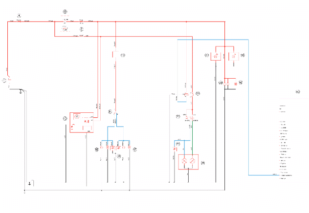
Devices and accessories
KEY
1. Battery
4. Main fuse
5. Ignition switch
6. Secondary fuses
10. Instrument panel
11. MODE button
13. Pre-installation for anti-theft device
26. Saddle opening actuator
27. Horn button
28. Horn
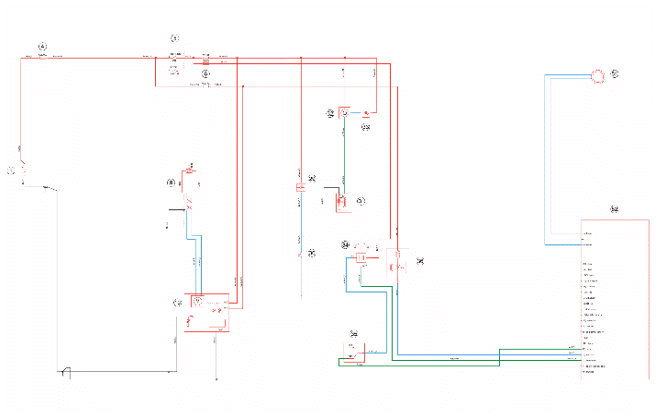
Lights and turn indicators
Versions for market USA-CND
KEY
1. Battery
4. Main fuse
5. Ignition switch
6. Secondary fuses
10. Instrument panel
12. Turn indicator control
14. Turn indicator switch
15. Left turn indicator bulbs
16. Turn indicators warning lights
17. Right turn indicator bulbs
18. Stop light
19. Stop buttons
22. High beam warning light
23. Light switch
24. Headlight relay
25. Headlight
37. Left front daylight running light
38. Right front daylight running light
39. Rear daylight running light
40. License plate light
52. Injection ECU
INJECTION
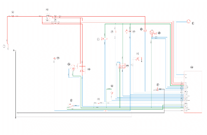
KEY
1. Battery
4. Main fuse
5. Ignition switch
6. Secondary fuses
21. Starter relay coil
34. Roll-over sensor
35. engine stop switch
36. Immobilizer LED
41. Injector
42. Idle valve
43. Engine speed sensor
44. Engine temperature sensor
45. Lambda probe
46. Fuel pump
47. HV coil
48. Injection warning light
49. Throttle body position
50. Diagnostics socket
51. Immobilizer aerial
52. Injection ECU
See also:
 Vespa Primavera 50 - Service manual > Components arrangement
1. RIGHT HAND STOP SWITCH Remove the upper handlebar cover to reach it.
Vespa Primavera 50 - Service manual > Checks and inspections
Immobiliser The electronic ignition system is controlled by the control unit with the integrated Immobilizer system. The immobiliser is an antitheft system which allows the vehicle to function only if it is activated by means of the coded keys that the control unit recognises. The code is integrated in a transponder in the key block. This allows the driver clear operation without having to do anything other than just turning the key. The Immobilizer system consists of the following components: Control unit Immobilizer antenna master and service keys with built-in transponder HV coil diagnosis LED
 BMW R 1250 RT
 Kymco Agility 50
 Piaggio Liberty 50
 Yamaha aerox NS50
 Aprilia SR50R
 Kymco Agility 50
 Vespa Primavera 50
 Peugeot Speedfight