 Kymco Agility 50 - Service manual > Handlebar switches
INSPECTION
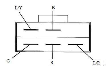
Remove the handlebar front cover. Disconnect the handlebar switch couplers and check for continuity between wire terminals.
If there is any abnormality found, check each switch.
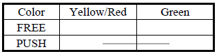
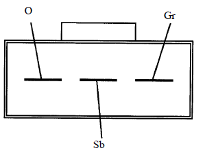
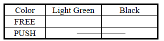
HEADLIGHT SWITCH
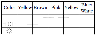
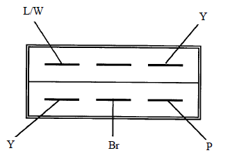
Use the X1 range for
test when using an electric tester.
range for
test when using an electric tester.
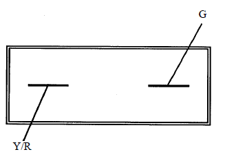
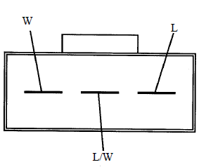
STARTER SWITCH
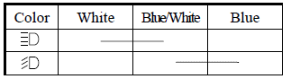
DIMMER SWITCH
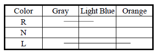
TURN SIGNAL SWITCH
HORN SWITCH
SWITCH REPLACEMENT
Remove the front covers. Remove the handlebar front cover. The installation sequence is the reverse of removal.
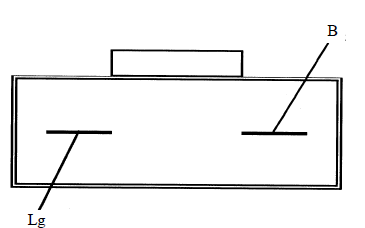
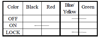
IGNITION SWITCH
INSPECTION
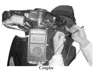
Remove the front covers. Disconnect the ignition switch wire coupler.
Check for continuity between the wire terminals.
IGNITION SWITCH REPLACEMENT
Remove the front covers.
Disconnect the ignition switch wire coupler.
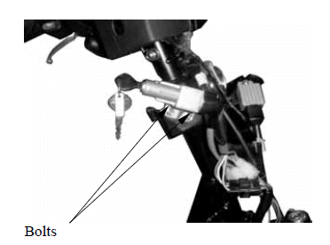
Remove the two mounting bolts to remove the ignition switch decorative ring and holder.
Remove the two screws to remove the ignition switch from the ignition switch holder for replacement.
The installation sequence is the reverse of removal.
STOP SWITCHES/HORN
STOP SWITCH
INSPECTION
Remove the handlebar front cover. Disconnect the front stop switch wire coupler.
Check for continuity between the wire terminals when the front brake lever is applied. The switch is normal if there is continuity.
Disconnect the rear stop switch wire coupler.
Check for continuity between the wire terminals when the rear brake lever is applied.
The switch is normal if there is continuity.
HORN
INSPECTION
Remove the front covers.
Disconnect the horn wire coupler.
The horn is normal if it sounds when a 12V battery is connected across the horn wire terminals.
REPLACEMENT
Disconnect the horn wire coupler.
Remover the two bolts attaching the horn.
Remove the horn.
The installation sequence is the reverse of removal.
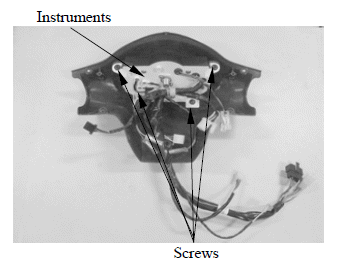
INSTRUMENTS
Remove the handlebar front cover.
Remove the handlebar rear cover.
Disconnect the handlebar switch couplers.
Remove the three screws to remove the instruments.
Install a new horn in the reverse order of removal.
See also:
 Kymco Agility 50 - Service manual > Service information
GENERAL INSTRUCTIONS An electric tester is needed to measure or test the electric equipment. Be sure to use fuses and bulbs of the same specifications to avoid damage of electrical equipment. After installation of each switch, a continuity check must be performed. A continuity check can usually be made without removing the part from the motorcycle.
Kymco Agility 50 - Service manual > Headlight
REMOVAL Remove the screw on the front of the front cover. Remove the six screws on the back of the front cover. Remove the front cover. The installation sequence is the reverse of removal. Align the tab on the headlight with the groove on the handlebar cover. After installation, adjust the headlight beam.
 BMW R 1250 RT
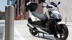 Kymco Agility 50
 Piaggio Liberty 50
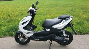 Yamaha aerox NS50
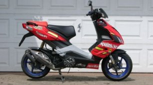 Aprilia SR50R
 Kymco Agility 50
 Vespa Primavera 50
 Peugeot Speedfight