 Vespa Primavera 50 - Service manual > Starter motor
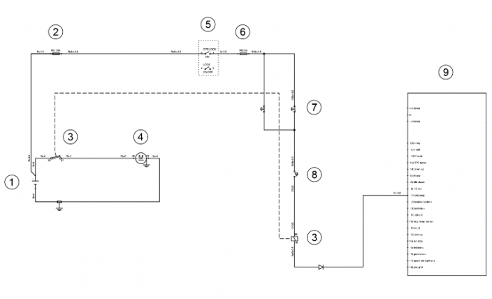
- Battery
- Fuse No. 1
- Starter relay
- Starter motor
- Ignition switch
- Fuse no. 2
- Stop buttons
- Starter button
- CDI control unit
Horn control
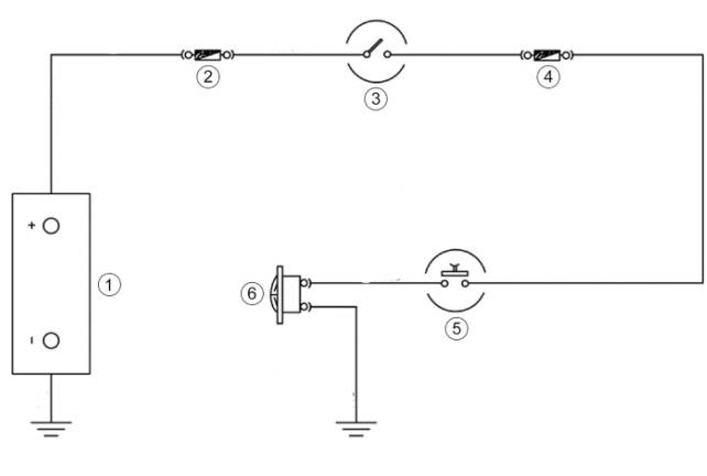
- Battery
- Fuse No. 1
- Ignition switch
- Fuse no. 2
- Horn button
- Horn
Turn signals system check
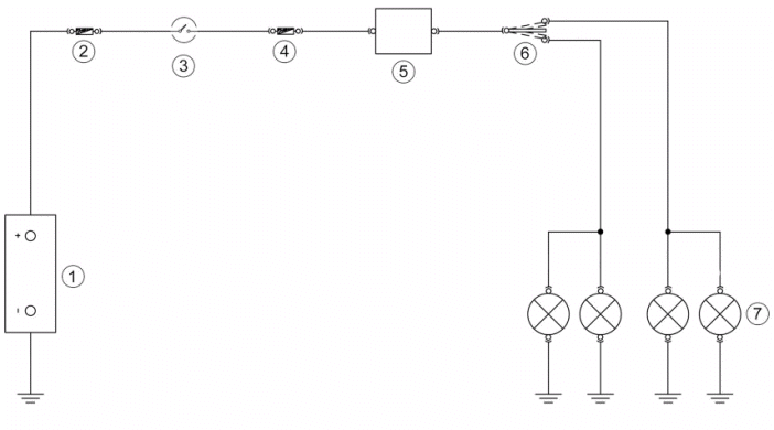
- Battery
- Fuse No. 1
- Ignition switch
- Fuse no. 2
- Turn indicator device
- Turn indicator switch
- Turn indicators
Level indicators
WARNING
ALL CONTINUITY TESTS MUST BE CARRIED OUT WITH THE CORRESPONDING CONNECTORS DISCONNECTED.
If faults are detected:
1) With a multimeter, check resistance values between the White-Green cable and the Black cable of the fuel level transmitter under different conditions.
2) If the transmitter operates correctly but the indication on the instrument panel is not exact, check that the cable harnesses between them are not interrupted.
Electric characteristic
Resistance value with full tank
<= 7 Ω
Resistance value with empty tank
90 +13/-3 Ω
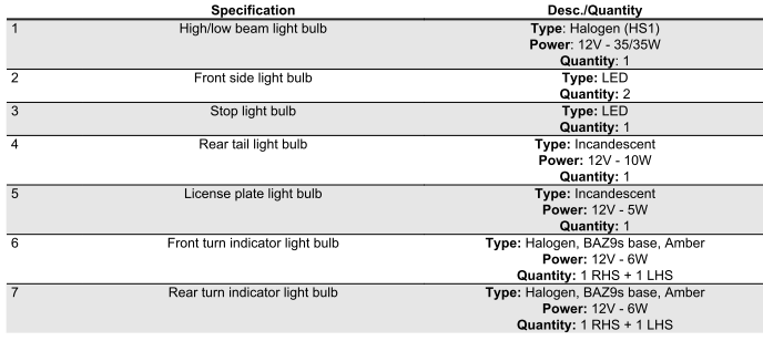
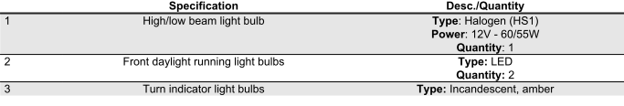
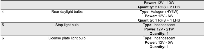
Lights list
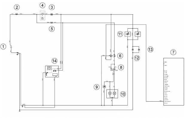
- Battery
- Fuse No. 1
- Fuse no. 2
- Ignition switch
- Fuse No. 5
- Light solenoid
- CDI control unit
- Light switch
- High beam warning light
- Headlight
- Front daylight running light
- License plate light
- Rear daylight running light
- Instrument panel lighting
BULBS
Versions for market USA-CND
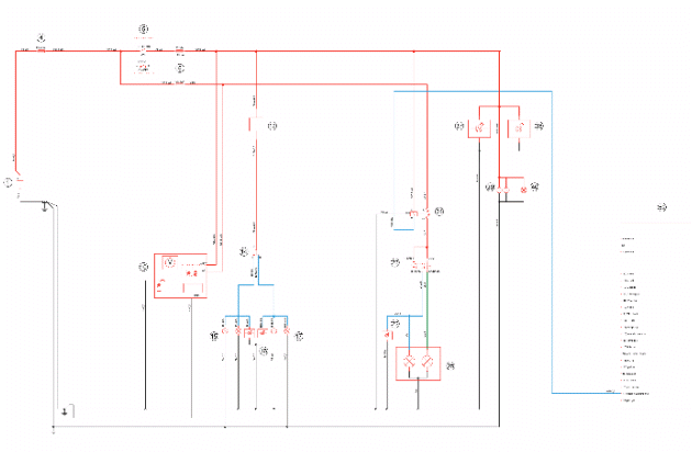
- Battery
- Fuse No. 1
- Fuse no. 2
- Ignition switch
- Fuse No. 5
- Light solenoid
- CDI control unit
- Light switch
- High beam warning light
- Headlight
- Front daylight running light
- License plate light
- Rear daylight running light
- Instrument panel lighting
BULBS
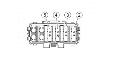
Fuses
The electrical system is protected by a main fuse and four secondary fuses, positioned as:
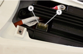
MAIN FUSE HOLDER "A": battery compartment.
Access to main fuse "A":
- Remove the battery compartment cover as described in "Battery" paragraph.
- Open the fuse holder.
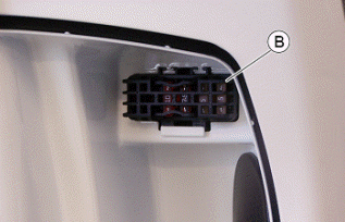
SECONDARY FUSES "B": inside the front case.
Access to the secondary fuses "B":
- Open the front case.
- Open the fuse holders.
CAUTION
BEFORE REPLACING THE FUSE IT IS NECESSARY TO FIND AND SOLVE THE FAILURE THAT CAUSED IT TO BLOW.
DO NOT REPLACE THE FUSE WITH ANY ALTERNATIVE FORM OF CONDUCTOR.
CAUTION
IN ORDER TO AVOID DAMAGING THE ELECTRIC SYSTEM, NEVER DISCONNECT THE WIRING WHILE THE ENGINE IS RUNNING. DO NOT TIP THE VEHICLE TOO MUCH IN ORDER TO AVOID DANGEROUS LEAKAGE OF THE BATTERY ELECTROLYTE.
CAUTION
MODIFICATIONS OR REPAIRS TO THE ELECTRICAL SYSTEM, PERFORMED INCORRECTLY OR WITHOUT STRICT ATTENTION TO THE TECHNICAL SPECIFICATIONS OF THE SYSTEM CAN CAUSE MALFUNCTIONING AND RISK OF FIRE.
CAUTION
PROCEED WITH CAUTION.
DO NOT DAMAGE THE TONGUES OR THEIR SEATS. HANDLE THE PAINTED AND PLASTIC COMPONENTS CAREFULLY. DO NOT SCRATCH OR DAMAGE THEM.
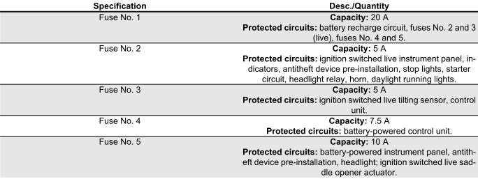
FUSE CHART
Dashboard
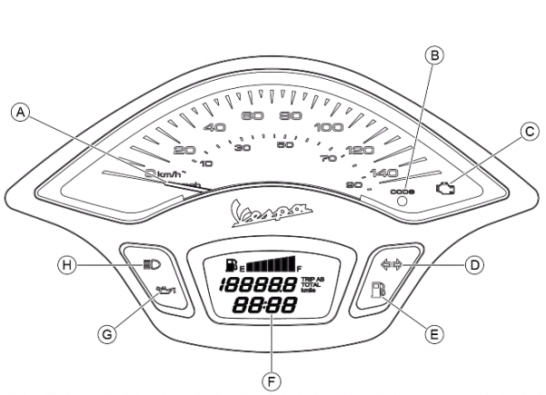
- Speedometer
- Immobilizer LED
- Engine control warning light
- Turn indicator warning light
- Low fuel warning light
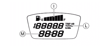
- Digital display
- Low engine oil pressure warning light
- High-beam headlight warning light
- Fuel gauge with petrol symbol
- Total or partial odometer
- Clock
Sealed battery
If the vehicle is provided with a sealed battery, the only maintenance required is the check of its charge and recharging, if necessary.
These operations should be carried out before delivering the vehicle, and on a six-month basis while the vehicle is stored in open circuit.
Besides upon pre-delivery it is therefore necessary to check the battery charge and recharge it, if required, before storing the vehicle and afterwards every six months.
INSTRUCTIONS FOR BATTERY REFRESH AFTER OPEN CIRCUIT STORAGE
1) Voltage check
Before installing the battery on the vehicle, check the open circuit voltage with a standard tester.
- If voltage exceeds 12.60 V, the battery can be installed without any renewal recharge.
- If voltage is below 12.60 V, a renewal recharge is required as explained in 2).
2) Constant voltage battery charge mode
- Constant voltage charge equal to 14.40 to 14.70V
- Initial charge voltage equal to 0.3 to 0.5 for Nominal capacity
- Charge time:
10 to 12 h recommended
Minimum 6 h
Maximum 24 h
3) Constant current battery charge mode
- Charge current equal to 1/10 of the battery rated capacity
- Charge time: Maximum 5 h
See also:
 Vespa Primavera 50 - Service manual > Checks and inspections
Immobiliser The electronic ignition system is controlled by the control unit with the integrated Immobilizer system. The immobiliser is an antitheft system which allows the vehicle to function only if it is activated by means of the coded keys that the control unit recognises. The code is integrated in a transponder in the key block. This allows the driver clear operation without having to do anything other than just turning the key. The Immobilizer system consists of the following components: Control unit Immobilizer antenna master and service keys with built-in transponder HV coil diagnosis LED
Vespa Primavera 50 - Service manual > Battery installation
VRLA battery (valve-regulated lead-acid battery) Maintenance Free (MF) WARNING BATTERY ELECTROLYTE IS TOXIC AND IT MAY CAUSE SERIOUS BURNS. IT CONTAINS SULPHURIC ACID. AVOID CONTACT WITH YOUR EYES, SKIN AND CLOTHING. IF IT ACCIDENTALLY COMES INTO CONTACT WITH YOUR EYES OR SKIN, WASH WITH ABUNDANT WATER FOR APPROX. 15 MIN. AND SEEK IMMEDIATE MEDICAL ATTENTION.
 BMW R 1250 RT
 Kymco Agility 50
 Piaggio Liberty 50
 Yamaha aerox NS50
 Aprilia SR50R
 Kymco Agility 50
 Vespa Primavera 50
 Peugeot Speedfight